Thanks @norb
Yes i have also seen The front end from hifiocean and I have previously also contacted him to ask if he had any plans to do a PSU board as well. Unfortunately he only has the front end.
You design looks good as well, but mine and my friend are both wired with a separate PSU.
So the original design, or close too, is probably the first choice🙂
Hi @miklau, thanks for the suggestion. That's an issue I wasn't expecting.
I assembled my front end completely discretely and already completed the board, so it should be pretty troublesome to have the MOSFETs have common heatsink. I think I will just have to see how it goes.
If you are looking for Gerber files, the original Part 2 article has both the images of front end and PSU, and both sides for both.
Not sure how troublesome it is to manually convert it to Gerber, but definitely much better than nothing already.

Need some guidance on this schematic
On the power supply drawing there is a spike suppressor/absorber (TZ1-400V) that is confusing me because I can't find anything similar (Symbol wise) the ones I can find are Diodes (TVS) or capacitors (X2 type).
Can anybody advise on a suitable replacement for it ?
On the power supply drawing there is a spike suppressor/absorber (TZ1-400V) that is confusing me because I can't find anything similar (Symbol wise) the ones I can find are Diodes (TVS) or capacitors (X2 type).
Can anybody advise on a suitable replacement for it ?
Last edited:
Try looking at this. Maybe just some inspiration.
There are also Gerber files for that
https://www.diyaudio.com/community/threads/nelson-pass-a75-a40.406911/
There are also Gerber files for that
https://www.diyaudio.com/community/threads/nelson-pass-a75-a40.406911/
Attachments
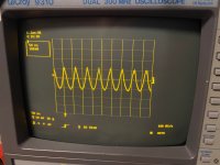
Hello fellows, finally start testing front stage, would like some help here.
I got all the numbers matched as described in the original paper, except the output offset won't go to below 50mV.
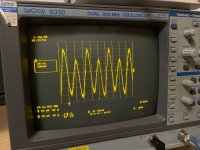
Best number I got was 1.3V, with R7 R8 very close to 1V. I tested 1 channel tonight and this is the non-match figure I got, will see what happens with the other channel in the morning.
I haven't hook up everything, am testing the front stage with regulated power supply only.
I also didn't 'see the clipping by turning up source'. I went to 400mV and didn't see clipping and dared not keep going up.
And I wonder if this is the 'clean wave form' I should be getting.
Or just that depending on the oscilloscope capability this could be the best resolution I can get? First time with oscilloscope.
I got all the numbers matched as described in the original paper, except the output offset won't go to below 50mV.
Best number I got was 1.3V, with R7 R8 very close to 1V. I tested 1 channel tonight and this is the non-match figure I got, will see what happens with the other channel in the morning.
I haven't hook up everything, am testing the front stage with regulated power supply only.
I also didn't 'see the clipping by turning up source'. I went to 400mV and didn't see clipping and dared not keep going up.
And I wonder if this is the 'clean wave form' I should be getting.
Or just that depending on the oscilloscope capability this could be the best resolution I can get? First time with oscilloscope.
Attachments
Adjust P1 or P2 to bring the offset down. The voltage across R7 and R8 is not critical. They don't need to be exactly the same. When you test the output stage the offset will most likely need to be adjusted again.
You would only see the clipping as you first started turning up the bias with P1 and then P2. Clipping would occur when Q3 or Q6 is not conducting enough to pass the signal because of the lack of voltage provided by P1 and/or P2. When you first adjust one of the pots, one of the mosfets would conduct while the other would still be turned off. Then you would adjust the other pot and see the other half of the signal.
You would only see the clipping as you first started turning up the bias with P1 and then P2. Clipping would occur when Q3 or Q6 is not conducting enough to pass the signal because of the lack of voltage provided by P1 and/or P2. When you first adjust one of the pots, one of the mosfets would conduct while the other would still be turned off. Then you would adjust the other pot and see the other half of the signal.
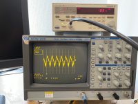
Noob question here.
The Ground clip of oscilloscope probe is supposed to connect to A75 GND right?
I noticed by unhooking the Ground clip I got an OK sine wave, looks sine enough.
With Ground clip connected to a GND point on A75, I am never able to get a sine wave. Looks a bit sine but probably not really sine.
The oscilloscope probably should connect to a signal ground..? But as I said with Ground clip connected I really can't reach a since wave.
Attachments
Can you measure your signal generator output?
If the O-scope is not isolated, you don't need to connect the probe ground clip. All measurements will be referenced to ground.
Adjust the time base so that one cycle can be measured. This will equal one millisecond. Time =1/1000Hz
If the O-scope is not isolated, you don't need to connect the probe ground clip. All measurements will be referenced to ground.
Adjust the time base so that one cycle can be measured. This will equal one millisecond. Time =1/1000Hz
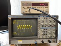
Hi everyone, got another question about output wave.
When testing second channel I noticed the wave looked noisy so I tried some display setting on my scope.
I can get a clean-looking wave if I set Trigger to sample positive of the slope, but the wave amplitude fluctuated, though in a coherent manner.
If Trigger was set to negative of slope, which the scope always set automatically, the wave looked noisy, and maybe also not perfectly symmetrical.
I am not really experienced with checking wave form of amplifier (trying to figure out at the moment),
but for A75 is this something that needs checking? If there is anything on my circuit I should be checking.
Attachments

The A75 is a great amplifier. You just have to be very careful when assembling and very patient when reviving. Mine worked the first time it was plugged in. At least I thought so. The measurements and the oscilloscope were completely fine. Only after connecting the headphones did I hear a big hum. I had an error in the power supply of the +/- 50V input stage. I wired it wrong.
It is very important to check the power supply. When testing the input stage, connect at least one pair of output power transistors and you can connect the output through some resistor to the headphones. The test power supply of the output transistors can be +/- 15V. It doesn't matter when testing. I've always done it that way.
My A75 could be set to an output offset below 10mV. It went around zero, but I still used a DC servo. And it works perfectly. When testing - input signal - sine, set for example to 50mV to 100mV and 1kHz. I wish you a lot of luck and patience. But you will see that it will be worth the work.
Attachments
Hi guys, thanks for helping out and suggestions.
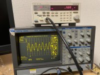
Wanting to A/B test and try the oscilloscope more, I tried empty load test (input unhooked, nothing no input) as well as signal generator load test again.
I was pretty surprised to find out how the waveform looked like with input unhooked and (1) power cord disconnected (2) power cord connected not powered-on, and I got essentially identical wave form with both channel.
Then I did load test again, this time using AC coupling and AC trigger setting on the scope.
With time drilled down properly I was able to get somewhat clean waveform. I had to go down to at least 50ns, with millisecond I would just get unreadable vibrating sharp waves. I got essentially same waveform with both channels, one of the channels looked a bit more noisy.
Looking at the waveform a bit I made this noob guess: Is this the so called second harmonics?
After doing some quick check, it totally looked like second harmonic in the wave.
(I am not complaining, just trying to figure out)
Attachments
What I'm suggesting is that you become familiar with the O-scope by using only the signal generator and O-scope connected together.@BDP
Do you mean meansuring IN+ and IN-?
I can got a few mV on my multimeter.
I quick searched a bit and also read that oscilloscope compares the signal to a reference ground already so the ground clip on the probe need not be hooked.
Setup your signal generator for 1000Hz sinewave and 1 volt amplitude. Connect your O-scope to the signal generator. Adjust the time (0.2 msec/div) and amplitude (0.5 volts/div) settings on the O-scope in order to see a waveform that fits on the display. Then measure the time between peaks of one cycle. What do you get? What is the amplitude voltage peak to peak?
Then try at 2000 Hz?
- Home
- Amplifiers
- Pass Labs
- circuit questions for Pass Thagard A75