NOTE: I don't see how to edit my previous post. Some of the rest of the thread apparently brings in corrugations, which is a different story than the Martin Logans.
You can edit posts within an hour, I have had to double post too because of that.
But yes, the membrane will be corrugated which will let it expand and contract slightly with less strain than if it was not corrugated.
And the physical curve is not meant to curve the sound in the normal sense. The curve represents a physical delay further up along the line array, where there is also an amplitude shading. The physical delay and the shading makes the speaker act as a Constant Beamwidth Transducer (CBT) which in my case makes it act as a much bigger dipole that is slightly squished in the vertical axis*. It lets me have an array that does not extend to the ceiling, but still measure as flat as if it did.
Also, I think the physical curve looks very nice 🙂
Simulation by keele of a dipole CBT:
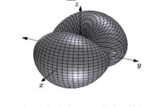
Links to the papers, the above figure is snipped from the first paper.
https://www.keele-omholt-technologi...ty-Circular-Arc-Arrays-of-Dipole-Elements.pdf
https://www.keele-omholt-technologi...tivity-Circular-Arc-Array-Manke-Eng-Brief.pdf
If you compare a flat panel of similar width whose entire area is playing midrange and up, you do see improvement in dispersion with the Martin Logan approach.the curve does not help the dispersion
Innersound Kaya
https://www.stereophile.com/content/innersound-kaya-reference-loudspeaker-measurements
Martin-Logan SL3
https://www.stereophile.com/content/martinlogan-sl3-loudspeaker-measurements-part-2
Last edited:
Yes, I think the start of the thread I riffed onto the usual curvature, but you are in the vertical dimension. Keele is a smart guy! Some related links, if nobody posted them yet. Funny that Wes Bender was working at a company making a FLAT (i.e. non-bent) panel! Then again I worked for a company making a speaker shaped like an ear.Constant Beamwidth Transducer
Very interesting-I might stand corrected (given different companies and construction...although that shouldn't matter to the diaphragm). Ya know it is just occurring to me that thinking of the curve projecting forward = same as a flat surface projecting forward is incomplete. The curvature will affect the off-axis phase-related dispersion, even if the sound is not radiating "radially" out from the panel.If you compare a flat panel of similar width whose entire area is playing midrange and up, you do see improvement in dispersion with the Martin Logan approach.
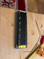
I have started the production line to glue all the magnets for 1 speaker, lots of work to do!
I have the measurments from the experiment last week though:
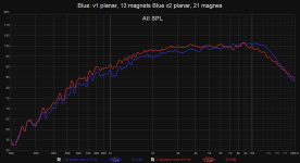
The bigger v2 planar is 62% so it makes sense for it to be slightly more efficient in the lower frequencies. Also a nice suprise that the bigger driver is smoother, so I can get away with less EQ to get a flat-ish response. The distortion is also lower. The full speaker will have 6x the length of the v2 planar, but with shading which reduces the output to ~ 70% across the whole driver.
And the polar response is excellent, same as the v1 experiment: (measurement is indoors, the 60-90 measurements are noisier than they could be but overall the measurements show that there are no glaring issues so good enough for me.

I have the measurments from the experiment last week though:

The bigger v2 planar is 62% so it makes sense for it to be slightly more efficient in the lower frequencies. Also a nice suprise that the bigger driver is smoother, so I can get away with less EQ to get a flat-ish response. The distortion is also lower. The full speaker will have 6x the length of the v2 planar, but with shading which reduces the output to ~ 70% across the whole driver.
And the polar response is excellent, same as the v1 experiment: (measurement is indoors, the 60-90 measurements are noisier than they could be but overall the measurements show that there are no glaring issues so good enough for me.

Some more progress!
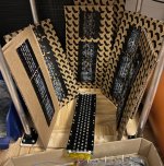
I now have enough steel plates with magnets glued to build 1 speaker! Only thing left is to reapply the black protective coat on the recently glued plates. The longer bottom plates are on the other side of the cardboard.
The plan for next weekend is to start cutting some membranes. I want to do AB (maybe even ABX) testing and compare if a thinner membrane (which is more difficult to cut and work with) sounds better or if it sounds the same if equalized. I also want to compare kapton vs mylar.
And then after that it is time to start attempting to cut the full length membrane. I will try to fix the process such that I can cut 20 um foil without rips but in case I don't then I can always use the 30 um with the thick pre applied acrylic adhesive. It is heavier than I would prefer, but it cuts like a dream with no rips.
I have now compared measured and subjectively compared membranes of different thicknesses. The configurations I compared are:
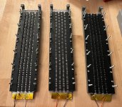
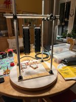
I measured them and then compared the results, here they are at 1W:
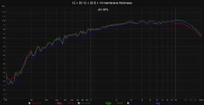
The differences were a lot more subtle than I thought they would be, considering that the lightest membrane is less than half the weight of the heaviest.
The thinnest membrane (which is a pain in the *** to cut and work with) is only more efficient than the heaviest above 7 khz. And the 20 um alu compromise arrangement is more efficient but only above 2 khz. And since most music has a power density of pink noise, where the power density falls off higher up in frequency then the most important region to be efficient is on the lower end.
I also measured distortion but it was within margin of error when SPL normalized so nothing exciting.
But now on to the subjective testing of sound quality!
I connected both the 12+30 and 6+14 drivers at the same time and SPL normalized them both to 400 hz LR4 highpass full range response. So I basically bumped the top end of the heavier membraned driver and added a slight notch for the lighter. Then I listened to some music and switched back and forth between the drivers.
And my conclusion is... I can't hear any difference at all. They sound the same. If there is a difference it is very subtle. Because I can't tell between the lighter and the heavier then I will decide membrane thickness based on other factors than the sound quality.
Next week I will do similar tests where I compare mylar vs kapton, but I assume those tests also will find no difference at all.
I have therefore decided that, if I can fix my technique such that I can cut 20 um aluminum foil consistently, then I will probably go with the 20 um alu but if I can't then I will use the heavier self adhesive 30 um alu. It might be the heaviest but it cuts like a dream, no rips at all.
The current TODO list:
- 12 um mylar + 30 um aluminum with 30 um self adhesive acrylic glue
- ~ 2.3 gram
- 2.63 ohm
- 12 um mylar + 20 um aluminum + light spray coat of Super 77 glue
- 1.2 gram
- 3.75 ohm
- 6 um mylar + 14 um aluminum + light spray coat of super 77 glue
- 0.9 gram
- 4.16 ohm


I measured them and then compared the results, here they are at 1W:

The differences were a lot more subtle than I thought they would be, considering that the lightest membrane is less than half the weight of the heaviest.
The thinnest membrane (which is a pain in the *** to cut and work with) is only more efficient than the heaviest above 7 khz. And the 20 um alu compromise arrangement is more efficient but only above 2 khz. And since most music has a power density of pink noise, where the power density falls off higher up in frequency then the most important region to be efficient is on the lower end.
I also measured distortion but it was within margin of error when SPL normalized so nothing exciting.
But now on to the subjective testing of sound quality!
I connected both the 12+30 and 6+14 drivers at the same time and SPL normalized them both to 400 hz LR4 highpass full range response. So I basically bumped the top end of the heavier membraned driver and added a slight notch for the lighter. Then I listened to some music and switched back and forth between the drivers.
And my conclusion is... I can't hear any difference at all. They sound the same. If there is a difference it is very subtle. Because I can't tell between the lighter and the heavier then I will decide membrane thickness based on other factors than the sound quality.
Next week I will do similar tests where I compare mylar vs kapton, but I assume those tests also will find no difference at all.
I have therefore decided that, if I can fix my technique such that I can cut 20 um aluminum foil consistently, then I will probably go with the 20 um alu but if I can't then I will use the heavier self adhesive 30 um alu. It might be the heaviest but it cuts like a dream, no rips at all.
The current TODO list:
- Subjective listening tests 12 um mylar vs 12 um kapton
- Improve cutting process for 20 um aluminum. The very successful solution I use with the 30 um self adhesive foil is to add a sticky plastic transfer paper on top before cutting. But it doesn't work as well on the thinner foil because without the thick acrylic glue the transfer paper is more sticky than the final glue so I can't get it off on the thinner foils! I have started playing around with making my own transfer paper with ReMount glue which does not stick as hard and it worked pretty well with thin paper but the paper ripped so some other thin material is probably better.
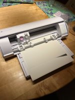 Photo is of a thick cardboard base with ReMount spray glue and then 14 um alu foil. Then a thin paper with ReMount glue on top. Worked great except where the paper ripped due to the trace gaps being so thin (0.5 mm).
 - Combine 2 driver lengths (52 cm tall, so 2/6 of a full driver) and make a rough speaker mockup where I mount woofers behind the drivers in kind of like a compact W frame like Gainphiles S20-Z, but where the woofer enclosure will be shaped like diamond instead of square to present less of an obstruction to the planar. Also with smaller drivers, up to 4" instead of 10" drivers (the plan is to progressivly use smaller drivers down to 2.5" on the top of the arc to allow it to be smaller on the top for aesthetical reasons). I hope that with a crossover as low as 400 hz I will be able to place the woofers at enough distance away from the planar such that the woofer enclosure won't impact the frequency response in a significant way, while still summing nicely in the crossover region.
- Full scale tests! But to do that I need to model the shaded membrane in CAD.
Last edited:
Great progress, OllBoll!
Yes, it's tricky to get a satisfying result.
The aluminium needs to be thick enough to keep the corrugation; to "win" over the plastic,.
But the ratio aluminium/plastic can't be too large as the membrane then cannot be considered stiff anyway; you'll get an imbalance between the driven and non-driven parts of the membrane which the corrugation were to mitigate in the first place.
Do you think that you put up some distortion measurements as well?
To be honest I got the result I was hoping for 😆
It is so much more fiddly to make the thin membrane and it is so much more fragile that I would strongly prefer if I could get a good enough result given my set of goals with a heavier membrane. And as luck would have it, I can.
Here are the distortion @4W:

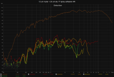
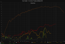
The distortion on the thin membrane is slightly lower, but it has slightly lower output. The distortion on the 20 um most likely has something rubbing so way off. I'll have to take it apart next weekend and se what is wrong with it. Probably wrongly mounted foam or the membrane has slid to the side too much.
Here is the normalized distortion:
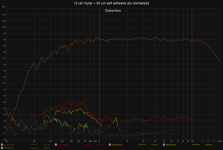
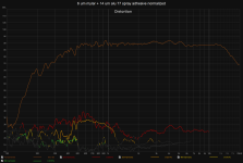
The thin membrane still has slightly less distortion but it is close enough that it is not clear if it is actually lower or just margin of error. Next weekend I can test with more thicker membranes + 1 with kapton and see if they too have the same distortion or if it is slightly lower. If I remember correctly my smaller experiments had distortion more in line with the thinner membrane hence my gut feeling that these values might be raised for some reason.
But in the end both distortion results are fine and within spec given my goal. Both should, when scaled up to 6x length (but shaded so in practice ~ 4x length in output), allow me to cross at 400-500 hz with minimal distortion compared to the woofers.
It is so much more fiddly to make the thin membrane and it is so much more fragile that I would strongly prefer if I could get a good enough result given my set of goals with a heavier membrane. And as luck would have it, I can.
Here are the distortion @4W:


The distortion on the thin membrane is slightly lower, but it has slightly lower output. The distortion on the 20 um most likely has something rubbing so way off. I'll have to take it apart next weekend and se what is wrong with it. Probably wrongly mounted foam or the membrane has slid to the side too much.
Here is the normalized distortion:


The thin membrane still has slightly less distortion but it is close enough that it is not clear if it is actually lower or just margin of error. Next weekend I can test with more thicker membranes + 1 with kapton and see if they too have the same distortion or if it is slightly lower. If I remember correctly my smaller experiments had distortion more in line with the thinner membrane hence my gut feeling that these values might be raised for some reason.
But in the end both distortion results are fine and within spec given my goal. Both should, when scaled up to 6x length (but shaded so in practice ~ 4x length in output), allow me to cross at 400-500 hz with minimal distortion compared to the woofers.
Thanks OllBoll.
How are the last two curves normalized? You aren't using REW's dBrelative scale?

How are the last two curves normalized? You aren't using REW's dBrelative scale?
Exactly, they are EQed equally in the DSP amplifier I have.Normalised should be "EQed equally"....?
I first used parametric eq filters in my Hyypex FA253 first to get the response close enough to the target response of 400 hz LR4 and flat elsewhere or flat + slightly too much. Then I measured again in REW and loaded up the EQ calculator and calculated any new notch biquads needed to get the target response. For the thin membrane it only needed to add a notch at the top end.
Then I repeated the process for the heavier membrane.
Ok, I understand.
But how can the normalized distortion curve differ that much from the non-normalized?
To the naked eye in 12+30 @4kHz they differ about 15dB.
But how can the normalized distortion curve differ that much from the non-normalized?
To the naked eye in 12+30 @4kHz they differ about 15dB.
The thin membrane seems to max out earlier. I first thought that it was a measurement error but ir persisted when I redid the measurement.
Here is 1-4 W for the thin membrane.
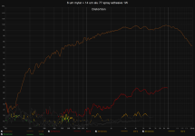
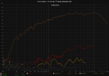
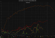
Compared to the thicker membrane:
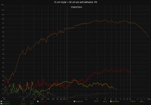
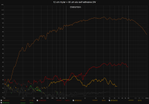
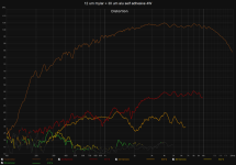
The distortion is smoothly increased when output in increased but no funny bump like the 4 khz in the thin membrane @ 4W. Except that my gut feeling tells me that something is wrong since the 3rd order should be less than 2nd harmonic, which it isn't at 1 khz @ 1W, which it has been in my other configurations. So it might be worth opening up this one too and see if something is wrong. Or since I have another identical membrane ready I can just screw together another one and test that one too and measure the difference between them.
Here is 1-4 W for the thin membrane.


Compared to the thicker membrane:


The distortion is smoothly increased when output in increased but no funny bump like the 4 khz in the thin membrane @ 4W. Except that my gut feeling tells me that something is wrong since the 3rd order should be less than 2nd harmonic, which it isn't at 1 khz @ 1W, which it has been in my other configurations. So it might be worth opening up this one too and see if something is wrong. Or since I have another identical membrane ready I can just screw together another one and test that one too and measure the difference between them.
Ok.
I still don't understand how the normalized distortion curve differ that much from the non-normalized.
Surely it cannot be the EQ alone.
I still don't understand how the normalized distortion curve differ that much from the non-normalized.
Surely it cannot be the EQ alone.
If one have a 6dB drop in level, the distortion would also be lower than if one EQed that drop to being 0 dB/falt. At least 6dB higher, probably more as the amplitude of the membrane need to be higher...
Buts not really "normalisation" - normalisation is done in a program for presentation reasons and no such is displayed above.
I never heard about a "normalised distortion curve" before... either distortion is measured on a driver/speraker "as is" or EQed flat.
//
Buts not really "normalisation" - normalisation is done in a program for presentation reasons and no such is displayed above.
I never heard about a "normalised distortion curve" before... either distortion is measured on a driver/speraker "as is" or EQed flat.
//
Yes, I understand that. But there must be more to if the difference is 15dB.
I use REW's dB relative setting to get an idea of how the distortion levels would be if EQ:ed flat.
Sorry for the bad wording, of "normalized distortion curve".
Please note that I am not trying to get a gotcha, I really want to know what's going on.
Another note is that I never EQ a drop; the whole frequency response is EQ:ed to the deepest drop to avoid clipping in the digital domain.
Why don't use thermoforming, it seems simplier and more accurate ?Great progress, OllBoll!
The aluminium needs to be thick enough to keep the corrugation; to "win" over the plastic,.
The trouble with thermoforming is that it is hard to do "molds" for any longer membranes.
Do you have any suggestion on how to accomplish it?
Do you have any suggestion on how to accomplish it?
- Home
- Loudspeakers
- Planars & Exotics
- DIY midtweeter planar, physically curved and shaded to be used in a dipole CBT
