I was randomly browsing back to the images of the first 12 + 20 um membrane which had horrible distortion and you can see the problem already in the images earlier in the thread:
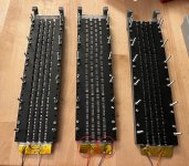
Here is a copy of the image but with red circles around the problematic areas. Notice especially that the aluminum foil has released completely from the underlying mylar and is loose between the mylar and the outer kapton tape. So I guess the kapton tape didn't stick that well either.
For the final membranes I will probably be more careful when I clean away the flux after soldering and then probably let them dry for a while before applying the kapton tape that helps to hold down the wires.
Good that you found the culprit!
I've tried to make solder joints like that, but haven't succeeded.
Probably because I'm not patient enough.
So I've gone back to the copper alligator clips that I used for my AMTs.

They've never failed me.
I've tried to make solder joints like that, but haven't succeeded.
Probably because I'm not patient enough.
So I've gone back to the copper alligator clips that I used for my AMTs.
They've never failed me.
Interesting.
I've also been playing around in my head with non solder methods of connecting the driver. I'm scared of oxidation though. Sure it might have low enough resistance in the beginning but will it increase over time? Or would it be good enough long term as long as I make the pad big enough? Say if I make like a square cm of pad around a screw hole connected to a ring terminal?
I've also been playing around in my head with non solder methods of connecting the driver. I'm scared of oxidation though. Sure it might have low enough resistance in the beginning but will it increase over time? Or would it be good enough long term as long as I make the pad big enough? Say if I make like a square cm of pad around a screw hole connected to a ring terminal?
Your worries are of course realistic. But as I'm not making speakers for others than myself, I take my chances.
And as I'm using 6µm aluminium foil it's very hard to make the soldering work.
Cue Wrinex...
And as I'm using 6µm aluminium foil it's very hard to make the soldering work.
Cue Wrinex...
And about soldering aluminum. The only problem I've had is that if I heat the alu too much it releases the glue to the backing mylar / kapton. When I use the kapton tape with the silicone glue it is less of a problem since the silicone adhesive can handle a lot higher temperatures.
But as long as I keep the joins small it works well enough with the 77 glue spray too. The technique with the most success so far is when I first apply AlumWeld Flux on the cable, then add some solder to the wire. Then also add a small blob of AlumWeld Flux to the aluminum pad, and then solder a small blob of solder. Then I add some more flux, place the solder-coated wire on top of the solder-blob and heat on top of the wire until it melts the solder and then release.
Works pretty well and has let me use a lot less solder while still getting the wires to stick to the aluminum. In fact on the leftmost membrane in the same image, which is the 20 um aluminum membrane I ripped a trace close to the pads when weeding. It was such a pain in the *** to cut on the plotter so before I did that I wanted to try to repair the trace, and with the above mentioned technique it worked great!
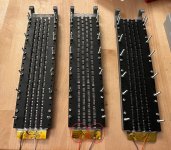
The repaired trace is on the leftmost driver at the bottom and has a purple box around it. The trace is 1.66 mm wide but it is hard to tell in the image.
EDIT:
I forgot that you work with annoyingly thin aluminum, here I sit where my "thin" aluminum is still 20 um thick and comparably very easy to solder 😆
But as long as I keep the joins small it works well enough with the 77 glue spray too. The technique with the most success so far is when I first apply AlumWeld Flux on the cable, then add some solder to the wire. Then also add a small blob of AlumWeld Flux to the aluminum pad, and then solder a small blob of solder. Then I add some more flux, place the solder-coated wire on top of the solder-blob and heat on top of the wire until it melts the solder and then release.
Works pretty well and has let me use a lot less solder while still getting the wires to stick to the aluminum. In fact on the leftmost membrane in the same image, which is the 20 um aluminum membrane I ripped a trace close to the pads when weeding. It was such a pain in the *** to cut on the plotter so before I did that I wanted to try to repair the trace, and with the above mentioned technique it worked great!

The repaired trace is on the leftmost driver at the bottom and has a purple box around it. The trace is 1.66 mm wide but it is hard to tell in the image.
EDIT:
I forgot that you work with annoyingly thin aluminum, here I sit where my "thin" aluminum is still 20 um thick and comparably very easy to solder 😆
A sneak peek of the shaded membrane in CAD:
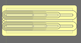
The reationale behind the traces is that the force is proportional to the current through the magnetic field, so if all traces carry the same current, then less traces means less output. I can use that to shade the membrane without loosing effiicency.
In reality it will be a lot longer, but to make it easier to see I've calculated as if the driver has 0.1 m radius rather than 1.5 m radius. When I am satisfied with everything else I will just restore the value to the true radius and recalculate.
I have tentatively decided to split the top and bottom into separate coils. That is because my estimate is that the resistance will be somewhere in the 22 ohm region which isn't crazy high but higher than I would prefer. With dual wirings I could, if I wanted to run both coils in parallel to bring the resistance down to 5.5 ohms.
The next steps are:
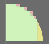
- Refine the exact widths of each shaded "bank" in the membrane. At the moment the transitions are like in the red lines, not like the green which is what I want:

- Add in membrane resistors to pad the 1/4 -6 dB to create -9 and -12 banks. The efficiency losses are minimal since 95% of the resistance is in the rest of the traces.
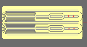
The exact length and thickness of the wire would need to be calculated too. - Cut foil of the -6 to -12 dB part with the resistors, then use my nifty 1 mOhm precision ohmmeter to measure the actual resistance and adjust the resistor trace lengths until I get the desired padding.
- Full scale cutting and full scale tests with shading!
Shading offsets calculated, should be close enough now.
I have also calculated what in theory should be the needed parallel resistor traces. If I assume 0.8 mm wide resistor traces where the normal single trace is the full width of 6 mm. Then the -9 dB resistor trace should be 156 mm long, and -12 dB resistor trace should be 51 mm long. These calculations should take into account that the resistors are not independent:
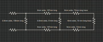
Next step is to add the resistor traces into the membrane at the appropriate place. And maybe calculate if I can get away with a thinner resistor trace like say 0.5 mm since it would let me get away with less resistor trace length. It looks like the area in between the main traces might become a bit crowded.


I have also calculated what in theory should be the needed parallel resistor traces. If I assume 0.8 mm wide resistor traces where the normal single trace is the full width of 6 mm. Then the -9 dB resistor trace should be 156 mm long, and -12 dB resistor trace should be 51 mm long. These calculations should take into account that the resistors are not independent:

Next step is to add the resistor traces into the membrane at the appropriate place. And maybe calculate if I can get away with a thinner resistor trace like say 0.5 mm since it would let me get away with less resistor trace length. It looks like the area in between the main traces might become a bit crowded.

First draft of in membrane shading. I decided to route the resistor traces "forwards" such that they add power rather than remove it. In practice this should slightly fill the bottom of the curve compared to the ideal curve, but not really in a significant way since the current is less. But at least I won't cancel signal which I would do if I routed them backwards.

With filling in the area where the signal is too little see the orange shaded area, the forwards traces are routed into these areas.
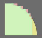
I guess the next step would be to try cutting the resistor parts of the membrane and then do some actual resistance measurements and see if my calculations are way off or close enough, and then adjust the length.
After shifting the shading to the left then the total resistance of the traces will be slightly less than before. My spreadsheet calculations predict it to be 18 ohms which is still more than ideal but not as bad as 22 ohm.
After testing in practice I might toy around with the idea of making the shading more granular by going down to -1.5 or -2 dB steps instead of -3 dB steps. The resistors should scale easily but I'd have to get creative in how I'd convert part of the dual-traced segment into a -1.5 dB. Maybe if I split the 6 mm trace into two parts where I route some part in the middle where the magnet field is strong, and another parallel trace which I move to the edges where the magnet field is less strong. Could be fun but would need testing 🙂

With filling in the area where the signal is too little see the orange shaded area, the forwards traces are routed into these areas.

I guess the next step would be to try cutting the resistor parts of the membrane and then do some actual resistance measurements and see if my calculations are way off or close enough, and then adjust the length.
After shifting the shading to the left then the total resistance of the traces will be slightly less than before. My spreadsheet calculations predict it to be 18 ohms which is still more than ideal but not as bad as 22 ohm.
After testing in practice I might toy around with the idea of making the shading more granular by going down to -1.5 or -2 dB steps instead of -3 dB steps. The resistors should scale easily but I'd have to get creative in how I'd convert part of the dual-traced segment into a -1.5 dB. Maybe if I split the 6 mm trace into two parts where I route some part in the middle where the magnet field is strong, and another parallel trace which I move to the edges where the magnet field is less strong. Could be fun but would need testing 🙂
Last edited:
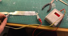
I did a test cut with the 30 um self adhesive alu since it cuts the easiest with my current technique:

Worked great except that the middle strip in between the resistor traces is crazy thin, I should probably remove it to avoid it causing problems when cutting.
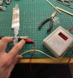
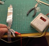
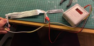
Then I cut into the membrane with a scissor and folded over the edges of the aluminum such that I can snap on ny clips easier.

Then I measured the resistance of each part:
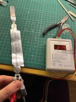 ...
...
And the resulting circuit is:
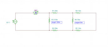
Where I have calculated that the resistors have too much resistance, both should have 83-84% of current resistances. I'll guesstimate how much less straight length that translates into and cut another membrane and measure again. And then repeat until I get within a few percent and call it good enough.
Doing these measurements gave me a reality check, I think for now I will stay at 3 dB steps. smaller steps is probably overkill and unneccesary complexity for now.

Worked great except that the middle strip in between the resistor traces is crazy thin, I should probably remove it to avoid it causing problems when cutting.
Then I cut into the membrane with a scissor and folded over the edges of the aluminum such that I can snap on ny clips easier.

Then I measured the resistance of each part:
 ...
...


And the resulting circuit is:

Where I have calculated that the resistors have too much resistance, both should have 83-84% of current resistances. I'll guesstimate how much less straight length that translates into and cut another membrane and measure again. And then repeat until I get within a few percent and call it good enough.
Doing these measurements gave me a reality check, I think for now I will stay at 3 dB steps. smaller steps is probably overkill and unneccesary complexity for now.
I've been cutting some more membranes but it got weird. I changed the length of the resistor traces but the resistances didn't change. In fact they were within 1 mOhm of the previous membranes.
Turns out that while I thought I changed the resistor lengths, I didn't. When I noticed that mistake I could get further and start dialing in the resistances. But based on that I have concluded that the resistances are very consistent between different membranes.
In fact consistency is so good that I have decided take a leap and try to go down to 2 dB steps. In the single trace part that is easy, I just need to add another resistor. Calculate rough starting length, cut, measure, iterate until satisfied, done.
The more complicated part is that on the part where I have 2 traces, I go from -3 dB to -6 dB when I go down from 2 to 1 traces. I need to add a pad in this transition, without adding a parallel resistor that shorts to the return trace since I still need the full power for the part afterwards which has a single full power trace netting -6 dB. Since I can't pad it I have been toying around with "creative solutions". One idea I have in my head that might work is to take advantage of the fact that the magnetic field is not uniformly strong across the whole width between the magnets. If I split the trace and route part of it just under the magnets then I think that should be less efficient than if I routed the traces in the middle like a sane person would.

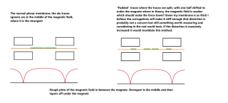
Or maybe the best way is not to split the trace but rather move the whole trace and then run the undriven fill in the middle where the field is the strongest.
In the end I don't need it to be perfect, just good enough to pad down -1.0 to -1.5 dB without impacting distortion in a significant way. My hope is that while the field is less linear to the sides the membrane is still stiff enough such that the effect is negligable. It will also not be pushed as hard as the parts with more traces so even it does distort more that might be OK.
If it doesn't work then unless I come up with a better idea then I'll have to settle at 3 dB steps.
Turns out that while I thought I changed the resistor lengths, I didn't. When I noticed that mistake I could get further and start dialing in the resistances. But based on that I have concluded that the resistances are very consistent between different membranes.
In fact consistency is so good that I have decided take a leap and try to go down to 2 dB steps. In the single trace part that is easy, I just need to add another resistor. Calculate rough starting length, cut, measure, iterate until satisfied, done.
The more complicated part is that on the part where I have 2 traces, I go from -3 dB to -6 dB when I go down from 2 to 1 traces. I need to add a pad in this transition, without adding a parallel resistor that shorts to the return trace since I still need the full power for the part afterwards which has a single full power trace netting -6 dB. Since I can't pad it I have been toying around with "creative solutions". One idea I have in my head that might work is to take advantage of the fact that the magnetic field is not uniformly strong across the whole width between the magnets. If I split the trace and route part of it just under the magnets then I think that should be less efficient than if I routed the traces in the middle like a sane person would.


Or maybe the best way is not to split the trace but rather move the whole trace and then run the undriven fill in the middle where the field is the strongest.
In the end I don't need it to be perfect, just good enough to pad down -1.0 to -1.5 dB without impacting distortion in a significant way. My hope is that while the field is less linear to the sides the membrane is still stiff enough such that the effect is negligable. It will also not be pushed as hard as the parts with more traces so even it does distort more that might be OK.
If it doesn't work then unless I come up with a better idea then I'll have to settle at 3 dB steps.
Last edited:
In the rightmost setup, you'll have more distortion than the setup to the left due to that the magnetic flux density is less linear in the y-direction between the magnets.
Even if corrugation might mitigate that, the total force from the strips on the membrane will vary as the membrane moves in the y-direction resulting in compression or de-compression of the output acoustic power when the input power increases. See this post.
On the other hand, the above is just one part of the total distortion and as such could be masked by other distortion components.
If you want to drive the membrane with equal force (lowest distortion!?) over the whole membra surface, one need to increase the current density where the field is weaker so that every individual mm2 sees the same F=BIL at any time during a full sine wave. The would reverse your presented strategy above wrt to placing the traces center/side!?
//
//
Yes it will most likely distort more than a conventional membrane at the same SPL. But will it distort more while playing at -4.5 dB compared to the conventional membrane playing at -0 dB?In the rightmost setup, you'll have more distortion than the setup to the left due to that the magnetic flux density is less linear in the y-direction between the magnets.
I think the only way to really know is to build 4 membranes:
- conventional with 4 traces, used as max SPL reference
- conventional with 2 traces
- The suggested membrane in my last post, where each trace splits where some part of it (say half) is routed to the side under the magnets

- Similar to above but without the split trace, just route the trace to the side and have the undriven fill in the middle of the magnet gap

Thats the thing, I do not want to drive the membrane with equal force over the whole membrane. In fact I want the opposite.If you want to drive the membrane with equal force (lowest distortion!?) over the whole membra surface, one need to increase the current density where the field is weaker so that every individual mm2 sees the same F=BIL at any time during a full sine wave. The would reverse your presented strategy above wrt to placing the traces center/side!?
I am not building a floor to ceiling array but rather a power shaded CBT array. Like this https://www.xlrtechs.com/dbkeele.com/CBT.php but with a cosine shading function instead of a legendre function since the cosine function works better for a dipole.
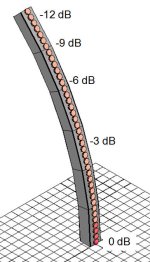
In a conventional CBT with multiple drivers that is usually done with a passive resistor network where the drivers are combined in banks and then padded down with resistors + clever use of resistances such that the end effect is that the drivers have the output reduced.
Here for example is the shading network of my previous 24 driver full range dipole CBT:
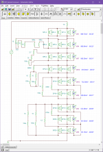
In practice I want that, but without having to resort to external components for the planar membrane. I want to wire the shading network into the actual membrane, while being as efficient as possible.
That is why I am routing 4 traces in the bottom most part of the membrane, and then progressively less traces further up and then padding when already at a single trace. Since all traces will be driven with the same amount of current, the only way I can apply less force is to have less traces in a given area. Except in the area where I want to try to apply less force without adding a parallel resistor but by moving the traces to where the field is weaker. Which might be a very dumb idea and it could be such that it is better to just accept that 3 dB steps are the lesser evil.
EDIT:
I was writing a long rebuttal of how I need multiple traces since the most simple solution which is a single trace would not work, but I think it would. If I only ran a single trace, I would not need any creative solutions where I move the traces outside the linear region but could rather just run a lot of parallel resistors. I could even make it such that route the resistor traces in the normal trace width and take them into account when calculating the applied force. In that case there would be almost no efficiency loss since there would be almost no true parallel resistors that exist just to burn voltage, the resistors would generate force too.
The big downside with the single trace strategy is that given 20 um alu foil the membrane would have very low resistance. I calculate ~ 1.7 ohm which is way less than I want.
I just got a crazy idea. A way to run 2 traces while still being able to run the parallel resistors (where my current method only works with a single trace) while also having other benefits.
What if I ran traces on both sides of the kapton? It would be heavier, yes, but with some clever tricks I believe I could get the weight to be comparable to my other membranes.
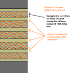
If I did the above, or in short.
Even if I don't do it because of the parallel resistor reasons, it would be fun to try it and compare the distortion if I can make a membrane of otherwise equal weight.
The more I think about it the more convinced I become that I just have to try it! I think I will try this first and then depending on what results I find either continue to investigate or go back to investigating the shading with a standard single sided membrane.
What if I ran traces on both sides of the kapton? It would be heavier, yes, but with some clever tricks I believe I could get the weight to be comparable to my other membranes.

If I did the above, or in short.
- Do not use a solid infill for the undriven areas but rather have sine wave squiggly lines in the previously filled area. With traces both on the top and bottom then those lines can overlap which should make them stiff enough to be comparable to a solid filled area. I could start with the thickness of the squiggly lines such that weight of the membrane is equal to a single sided membrane with solid infill. The edges that contact the foam strip should probably be solid though, but it would be enough for it to be solid on one side.
- Since we now have twice the thickness of the traces we could get away with half the width of the traces! This would reduce them to 3 mm which just happens to be the width that @solhaga has, in simulations found to be the most linear. Who know, maybe it performs much better when pushed such that it allows me to cross at 300-400 hz rather than 400-500 hz?
- Since each side is independent of the other, I can route parallel resistors like I tested this weekend for each side no problem. I could get away with only having parallel resistors along the whole length so I could have as many as 12 resistors for 1 dB steps.
- The resistance of both sides in series with the parallel resistors included should be in the region of 4 ohm if I go with the 30 um foil, or slightly higher if 20 um. While I would prefer 8-16 ohm, 4 ohm is still high enough to satisfy my "good enough" requirement.
- A challenge would be that I would need to very precicely apply the traces such that both sides line up. But my gut feeling tells me it should be possible.
Even if I don't do it because of the parallel resistor reasons, it would be fun to try it and compare the distortion if I can make a membrane of otherwise equal weight.
The more I think about it the more convinced I become that I just have to try it! I think I will try this first and then depending on what results I find either continue to investigate or go back to investigating the shading with a standard single sided membrane.
Last edited:
I threw together a simplified model:
First the standard membrane I've used so far. Single sided, 6 mm wide traces, 2 of them with a 0.5 mm gap in the middle

Now the fancy one:
The suspension infill and squiggly infill is on one side only, but the traces are on both sides. 3mm wide traces.
The infill is more sparse, but the traces are on both sides which should add a lot of stiffness. I think it should even out, maybe.
It will be very annoying to weed, but it is a rough test so that is fine. If it turns out this setup works well then I might play around with the design mentioned above since that one would be much easier to weed.
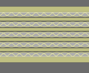
I trimmed the thickness of the squiggly lines such that both membranes will weigh the same. There is probably room to make the squiggly lines thinner but no such optimizations for now. The important thing is not to optimize it but to make it a fair comparison, hence making it comparable to the standard membrane such that it is a fair comparison.
First the standard membrane I've used so far. Single sided, 6 mm wide traces, 2 of them with a 0.5 mm gap in the middle

Now the fancy one:
The suspension infill and squiggly infill is on one side only, but the traces are on both sides. 3mm wide traces.
The infill is more sparse, but the traces are on both sides which should add a lot of stiffness. I think it should even out, maybe.
It will be very annoying to weed, but it is a rough test so that is fine. If it turns out this setup works well then I might play around with the design mentioned above since that one would be much easier to weed.

I trimmed the thickness of the squiggly lines such that both membranes will weigh the same. There is probably room to make the squiggly lines thinner but no such optimizations for now. The important thing is not to optimize it but to make it a fair comparison, hence making it comparable to the standard membrane such that it is a fair comparison.
Last edited:
I've been pondering about this myself. It can be hard to align both sides and I don't know if there will be a significant capacitance between the two layers.
So I did some test with non cut aluminium foil on both side of the PEN film and it was to my surprise harder to corrugate.
So I did some test with non cut aluminium foil on both side of the PEN film and it was to my surprise harder to corrugate.
It's vertically shaded yes but I mean horizontally...Thats the thing, I do not want to drive the membrane with equal force over the whole membrane. In fact I want the opposite.
//
Ah, then I misunderstood because you are absolutely correct. The ugly trick would be that the horizontal force is not equal, with the hope that the membrane is stiff enough that we can ignore the effect, which is a big maybe.It's vertically shaded yes but I mean horizontally...
I've been pondering about this myself. It can be hard to align both sides and I don't know if there will be a significant capacitance between the two layers.
So I did some test with non cut aluminium foil on both side of the PEN film and it was to my surprise harder to corrugate.
It would make sense to be harder to corrugate, it should be a lot stiffer. When write harder to corrugate do you mean that it did not hold corrugation as well or just more stiff and more difficult to work with? On Friday I will have access to the membrane materials and should be able test stiffness and maybe even cut a membrane.
- Home
- Loudspeakers
- Planars & Exotics
- DIY midtweeter planar, physically curved and shaded to be used in a dipole CBT