OK, but you could compensate for that by using thinner lines in the middle?
In theory, yes. Although we sill get the problems that the force is not as linear in the outer regions but it is probably something I will test and measure anyway so I know for sure.
It is, however, possible that while the distortion is say 2x at the same SPL of the conventionally routed traces, only ~ 35% of the max current will flow so in the end it might still distort less than the conventional traces.
Sorry, I got things mixed up. It is the plastic/aluminium/plastic that is problematic.
Aluminium/plastic/aluminium will corrugate fine.
I did a capacitance calculation of my mid membrane if I have aluminium/plastic/aluminium, it will be about 20 nF.
If you consider the resistance of the aluminium strips and the capacitance between them to be in parallell, you will have a LP cutoff frequency well above 1 MHz.

I finalized the CAD for the membranes I want to use to test single layer 6mm wide traces vs dual layer 3mm wide:


I am lazy so the squiggly membrane is symmetric, I can just cut two and weed the underside more by removing everything except the driven traces.
The squiggly pattern can probably be optimized, but should be good enough as a proof of concept. If I remember correctly from earlier experiments then large undriven areas mainly impact 5 khz+ range, but I am mostly interested in the bass region of 300-500 hz since it is there the distortion is the greatest.
I decided to do a small premature optimization: a lot of the squggly mass was concentrated towards the edges closer to the driven traces. I switched it around such that it is more evenly spread:

The weight is still the same.
The weight is still the same.
In the rightmost setup, you'll have more distortion than the setup to the left due to that the magnetic flux density is less linear in the y-direction between the magnets.
Even if corrugation might mitigate that, the total force from the strips on the membrane will vary as the membrane moves in the y-direction resulting in compression or de-compression of the output acoustic power when the input power increases. See this post.
On the other hand, the above is just one part of the total distortion and as such could be masked by other distortion components.
Since the idea of using dual 3 mm thick traces is to have as low distortion, I decided to re-print the +1 mm shims to bump the magnet to magnet gap from 3 mm to 4 mm, since I remeber you writing that you had much worse distortion @ 3 mm than @ 4 mm magnet-to-magnet gap. Which I think this figure shows.
I guess I could technically go down to 1 mm wide traces but then efficiency would go down the drain unless I have dual sided with 60 - 90 um thick alu... which would be quite chonky traces!
Yes it does.
Going down to 1 mm width will also be devastating for the force in the y-direction. In the qouted post in post #266 ,I started at 2.5 mm, here's how it looks with 1mm:
--> 1mm wide traces
-->
mm, N, % of zero % of previous
--> 0.00, 1.290568, +0.00, +0.00
--> 0.05, 1.290527, -0.00, -0.00
--> 0.10, 1.290300, -0.02, -0.02
--> 0.15, 1.289768, -0.06, -0.04
--> 0.20, 1.289521, -0.08, -0.02
--> 0.25, 1.289124, -0.11, -0.03
--> 0.30, 1.288492, -0.16, -0.05
--> 0.35, 1.287741, -0.22, -0.06
--> 0.40, 1.287046, -0.27, -0.05
--> 0.45, 1.285948, -0.36, -0.09
--> 0.50, 1.284782, -0.45, -0.09
--> 0.55, 1.283536, -0.55, -0.10
--> 0.60, 1.282060, -0.66, -0.12
--> 0.65, 1.280373, -0.80, -0.13
--> 0.70, 1.278874, -0.91, -0.12
--> 0.75, 1.277218, -1.05, -0.13
--> 0.80, 1.274886, -1.23, -0.18
--> 0.85, 1.272852, -1.39, -0.16
--> 0.90, 1.270018, -1.62, -0.22
--> 0.95, 1.266957, -1.86, -0.24
--> 1.00, 1.264536, -2.06, -0.19
With a +/- 0.5mm corrugation, you will have at least 0.1% (that is -60dB) distortion contribution for every 0.1mm movement of the membrane along with the compression (minus sign on all deviations from zero).
Compared to 3mm:
--> 3mm wide traces
-->
mm, N, % of zero % of previous
--> 0.00, 1.300010, +0.00, +0.00
--> 0.05, 1.300027, +0.00, +0.00
--> 0.10, 1.299981, -0.00, -0.00
--> 0.15, 1.300083, +0.01, +0.01
--> 0.20, 1.300114, +0.01, +0.00
--> 0.25, 1.300178, +0.01, +0.00
--> 0.30, 1.300283, +0.02, +0.01
--> 0.35, 1.300444, +0.03, +0.01
--> 0.40, 1.300421, +0.03, -0.00
--> 0.45, 1.300429, +0.03, +0.00
--> 0.50, 1.300453, +0.03, +0.00
--> 0.55, 1.300511, +0.04, +0.00
--> 0.60, 1.300567, +0.04, +0.00
--> 0.65, 1.300427, +0.03, -0.01
--> 0.70, 1.300302, +0.02, -0.01
--> 0.75, 1.299991, -0.00, -0.02
--> 0.80, 1.299357, -0.05, -0.05
--> 0.85, 1.299069, -0.07, -0.02
--> 0.90, 1.298484, -0.12, -0.05
--> 0.95, 1.297622, -0.18, -0.07
--> 1.00, 1.296849, -0.24, -0.06
Here you can have at least a +/- 0.75mm corrugation with none distortion contribution and none compression.
Again, if the are other distortion contributions that are a magnitude higher, none of the above matters.
I started cutting the dual sided membranes with the squiggly fill but it was a total failure. The design in https://www.diyaudio.com/community/...o-be-used-in-a-dipole-cbt.412132/post-7867902 is too much of a nightmare to weed. It also took ages to cut since the knife had to stop and turn so much to cut all the small holes.
I made a new design that will be a lot easier to weed and should cut a lot faster since while not straight cuts is mostly continous lines.
I will take advantage of placing the squiggly fill on both sides, so here is one side:

And then the underside mirrored vertically gives the following shape:

The outer suspension fill is something I plan to only have on the top layer, since one layer should be plenty stiff enough.
I made a new design that will be a lot easier to weed and should cut a lot faster since while not straight cuts is mostly continous lines.
I will take advantage of placing the squiggly fill on both sides, so here is one side:
And then the underside mirrored vertically gives the following shape:
The outer suspension fill is something I plan to only have on the top layer, since one layer should be plenty stiff enough.
Data from 3 mm wide dual sided traces!
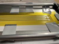
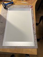
But first about cutting and gluing the multi layered membrane. The new squiggle pattern was much easier to weed, but still more work than straight cuts. I got the parts for my new membrane stretching jig though, and it worked great!


In the second image the bottom taped checkerboard strip with the traces is with the glue facing up, so to match the top and bottom I moved the pipe jig such that they overlap with ~ 2 mm gap and then when they were aligned I pushed it together and then rolled with a roller and it worked great!


And it turned out pretty stiff, which is cool:


The resistance was exactly as expected, ~ 1 ohm


The new dual sided membrane in the driver to the right.
Since there are so many images I'll add the performance graps in another post.
But first about cutting and gluing the multi layered membrane. The new squiggle pattern was much easier to weed, but still more work than straight cuts. I got the parts for my new membrane stretching jig though, and it worked great!
In the second image the bottom taped checkerboard strip with the traces is with the glue facing up, so to match the top and bottom I moved the pipe jig such that they overlap with ~ 2 mm gap and then when they were aligned I pushed it together and then rolled with a roller and it worked great!
And it turned out pretty stiff, which is cool:
The resistance was exactly as expected, ~ 1 ohm
The new dual sided membrane in the driver to the right.
Since there are so many images I'll add the performance graps in another post.
On the topic of performance though... it was both great and at the same time not good enough!
The dual sided uses 12 um kapton + 30 um aluminum with a somewhat heavy acrylic self adhesive.
To compare performance I picked the currently best membrane I have, which is the 12 um kapton + 12 um silicone glue + 20 um aluminum.

First both membranes at 8W. Ignore the distortion at 1.5 khz and upwards, that is just my microphone clipping.


The single sided lighter membrane which has 3 mm magnet-to-magnet gap is ~ 1.4 dB more efficient than the dual sided membrane with a 4 mm magnet-to-magnet gap. There might be room to reduce it somewhat by being clever but at most I think I could reduce it to 1 dB difference. 1 dB would be no big deal if the distortion is much better so good enough sensitivity.
The problem, however, is in the distortion. Or rather that the distortion is indeed lower, but not low enough.


Yes, the tall order distortions are way way lower in the dual sided membrane, but the 3rd order distortion is still way too high for my liking. Which means that in both of those cases, I'd want to cross higher to avoid both distortion peaks. In practice I'd probably cross both at more or less the same frequency which would be around 400 hz and above 400 hz, the wide traced variant even performs better since the 3rd order distortion is lower!
My guess is that while distortion due to magnet field differences is way less, there are still other causes of distortion that are big enough to make it less worth it. If the 3rd order distortion was 10-15 dB lower then it would be a no-brainer, but it isn't.
The more I think about it the more I come to the conclusion that those current measurements are interesting but they don't tell me how good they need to be. What is my target SPL? The single sided sure does distort a lot but only when I push a huge amount of power into it, more than 4 W which with all segments should be very loud already. Will I ever push it hard enough that the xmax related distortions become an actual problem?
I think I need to build a full scale driver with shading and all. Best is probably to not overcomplicate and go with the 3 dB stepped shading membrane from this and this post. Then I would be able to measure how good it actually performs. My gut feeling tells me that the distortion is already low enough, that if I cross at 400 hz @ LR4 then it will have basically no distortion all the way up to 106 dB @ 1m. And if that is true and the distortion is negligable, then I don't need the reduced magnet distortion since it is already low enough and would rather have the 1 dB gain in efficiency.
EDIT:
I also measured 0-90 polar, it was comparable to my other membranes.

The dual sided uses 12 um kapton + 30 um aluminum with a somewhat heavy acrylic self adhesive.
To compare performance I picked the currently best membrane I have, which is the 12 um kapton + 12 um silicone glue + 20 um aluminum.
First both membranes at 8W. Ignore the distortion at 1.5 khz and upwards, that is just my microphone clipping.
The single sided lighter membrane which has 3 mm magnet-to-magnet gap is ~ 1.4 dB more efficient than the dual sided membrane with a 4 mm magnet-to-magnet gap. There might be room to reduce it somewhat by being clever but at most I think I could reduce it to 1 dB difference. 1 dB would be no big deal if the distortion is much better so good enough sensitivity.
The problem, however, is in the distortion. Or rather that the distortion is indeed lower, but not low enough.
Yes, the tall order distortions are way way lower in the dual sided membrane, but the 3rd order distortion is still way too high for my liking. Which means that in both of those cases, I'd want to cross higher to avoid both distortion peaks. In practice I'd probably cross both at more or less the same frequency which would be around 400 hz and above 400 hz, the wide traced variant even performs better since the 3rd order distortion is lower!
My guess is that while distortion due to magnet field differences is way less, there are still other causes of distortion that are big enough to make it less worth it. If the 3rd order distortion was 10-15 dB lower then it would be a no-brainer, but it isn't.
The more I think about it the more I come to the conclusion that those current measurements are interesting but they don't tell me how good they need to be. What is my target SPL? The single sided sure does distort a lot but only when I push a huge amount of power into it, more than 4 W which with all segments should be very loud already. Will I ever push it hard enough that the xmax related distortions become an actual problem?
I think I need to build a full scale driver with shading and all. Best is probably to not overcomplicate and go with the 3 dB stepped shading membrane from this and this post. Then I would be able to measure how good it actually performs. My gut feeling tells me that the distortion is already low enough, that if I cross at 400 hz @ LR4 then it will have basically no distortion all the way up to 106 dB @ 1m. And if that is true and the distortion is negligable, then I don't need the reduced magnet distortion since it is already low enough and would rather have the 1 dB gain in efficiency.
EDIT:
I also measured 0-90 polar, it was comparable to my other membranes.
I think we need to understand what can cause high 3HD or odd harmonic distortion in general in a loudspeaker.
I asked ChatGPT:
Any thoughts?
I asked ChatGPT:
Key difference seems to be that 2HD is caused by asymmetries and 3HD by symmetries.Here’s a breakdown of the key differences between second and third harmonic distortion in loudspeakers:
Aspect Second Harmonic Distortion (SHD) Third Harmonic Distortion (THD) Harmonic Produced 2× the fundamental frequency 3× the fundamental frequency Cause Asymmetrical Nonlinearities Symmetrical Nonlinearities Suspension System Results from uneven stiffness (forward vs. backward) Results from symmetrical but nonlinear stiffness Magnetic Field Due to offset or asymmetry in the Bl curve Due to nonlinear force factor in both directions Motion Behavior Uneven diaphragm motion (e.g., asymmetric flexing) Uniform nonlinear motion (e.g., symmetric cone behavior) Electrical Input Affected by DC bias or asymmetrical amplifier response Affected by symmetric but nonlinear amplifier response Perception in Sound Adds overtones closer to the fundamental, sometimes "warming" Adds overtones farther from the fundamental, perceived as harsher Ease of Detection Harder to notice due to tonal similarity to the fundamental Easier to notice because it creates more distinct dissonance Measurement More significant at low frequencies Can occur across a wider frequency range Examples of Sources Offset magnetic gap, off-center voice coil, asymmetric spider stiffness Nonlinear Bl curve, suspension spring rate, material compression Impact on Sound Quality Can affect tonal balance, adding a "fat" or "colored" sound Leads to distortion perceived as "harsh" or "grainy" Summary
Reducing both is essential for clean and accurate sound reproduction, but they originate from fundamentally different mechanisms in the loudspeaker's design.
- Second harmonic distortion (SHD) is caused by asymmetrical issues in the design or operation, such as mechanical misalignment or offset components, and tends to add harmonics closer to the fundamental frequency.
- Third harmonic distortion (THD) arises from symmetrical nonlinearities, such as suspension or magnetic nonlinearities, and adds overtones that are farther from the fundamental, making it more noticeable.
Any thoughts?
Now that I have slept on it I have decided I want to investigate further.
I compared the efficiency and considering it is a heavy dual 30 um with heavy adhesive vs the much lighter 20 um with lighter glue the efficiency is not that different. It differs mostly in the bass and the treble, both of which are improved with a lighter membrane. I also looked at the distortion of the single sided self adhesive 30 um vs kapton tape glued 20 um and the 20 um has lower 3rd order distortion, on top of being more efficient.
My conclusion is that I need to make more membranes of different combinations.
I am looking at removing the squigglies too. The new variant with squiggly lines on each side was much easier to weed but still annoying. And since the pipe glue jig worked so great I think I can cut different parts of the membrane in different thicknesses and glue them together with high precision without any alignment issues. If anything cutting separately should be way easier since that in practice means I will not need to have the small 0.5 mm gap strips that are so prone to ripping or getting loose and ruining the cut.
So I will keep the non driven parts as solid filled areas, but in a thinner alu. For all I know the squigglies were the cause of the distortion. It will also make the comparisons more apples to apples since I will change less variables.
The different combinations I want to test are (12 um kapton for all membranes):
Number 4 should be slightly less efficeint than my best 6 mm wide membrane but should otherwise be the most comparable.
I compared the efficiency and considering it is a heavy dual 30 um with heavy adhesive vs the much lighter 20 um with lighter glue the efficiency is not that different. It differs mostly in the bass and the treble, both of which are improved with a lighter membrane. I also looked at the distortion of the single sided self adhesive 30 um vs kapton tape glued 20 um and the 20 um has lower 3rd order distortion, on top of being more efficient.
My conclusion is that I need to make more membranes of different combinations.
I am looking at removing the squigglies too. The new variant with squiggly lines on each side was much easier to weed but still annoying. And since the pipe glue jig worked so great I think I can cut different parts of the membrane in different thicknesses and glue them together with high precision without any alignment issues. If anything cutting separately should be way easier since that in practice means I will not need to have the small 0.5 mm gap strips that are so prone to ripping or getting loose and ruining the cut.
So I will keep the non driven parts as solid filled areas, but in a thinner alu. For all I know the squigglies were the cause of the distortion. It will also make the comparisons more apples to apples since I will change less variables.
The different combinations I want to test are (12 um kapton for all membranes):
- Filled areas: single side 20 um alu
Traces: dual side 30 um alu
Glue: 77 spray
- Filled areas: single side 14 um alu
Traces: dual side 20 um alu
Glue: 77 spray
- Filled areas: single side 14 um alu
Traces: dual side 14 um alu
Glue: 77 spray
- Filled areas: single side 20 um alu
Traces: single side 30 um alu
Glue: kapton tape silicone glue
- Filled areas: single side 14 um alu
Traces: single side 30 um alu
Glue: kapton tape silicone glue
Number 4 should be slightly less efficeint than my best 6 mm wide membrane but should otherwise be the most comparable.
Last edited:
I did some calculations.
I have played around in my head of an idea of using dual sided traces, but a single 3 mm trace on each side. And then do shading by running parallel resistor traces every -decibel or so. In theory I should be able to route the majority of the resistor length along the normal traces, which would then result in almost no loss in efficiency since the energy burned by the resistors contribute to the force.
I calculated the resistances and noticed some problems. On the top end of the driver, say where I go from 0 to -1 dB. I then have the main trace with ~ 0.51 ohm resistance, and I have 444 mm of space to route the resistor. The resistor should be ~ 4.2 ohm so easy peasy, I just calculate how wide the trace should be such that a 400 mm long trace has that resistance and it needs to be... oh... it needs to be 0.11 mm wide. Yeah that's not going to happen.
Not the end of the world though, I can still backtrack to the previous idea of using multiple traces and then returning them early like I outlined in this post. With 2 traces on each side I can use this method to bring down the power to -6 dB and then use the resistor method. When going from -6 dB to say -7.5-9 dB the resistor widths can be much wider thus being feasable to cut, as seen in the post afterwards where the resistor lengths and widths are managable, even if I halve them to account for 3 mm wide traces instead of 6 mm.
First membrane cut. traces are dual sided 20 um, the outer fill is 14 um.
I have not measured it yet, I will probably try to do that tomorrow.


Looks good so far, but soldering the wires was a disaster so it might be that the membrane will have the rattling problem of the wires as a previous membrane did. I have learnt some lessions so I'm thinking about redoing it with some fixes:
I have not measured it yet, I will probably try to do that tomorrow.
Looks good so far, but soldering the wires was a disaster so it might be that the membrane will have the rattling problem of the wires as a previous membrane did. I have learnt some lessions so I'm thinking about redoing it with some fixes:
- I got too greedy with trace gap margin, the above membrane has 2 traces with a 0.4 mm gap. It was pretty annoying to cut and I only got it to work when using vinyl transfer sheets as protection but then it was annoying to de-weed the transfer sheet without hurting the foil. I think I can solve this by going down to a single trace and bumping the gap margins to 0.75 mm.
- The trace pads release from the membrane when soldering! Or at least, they do when I use the thinner 77 spray glue. I think I can solve that by copying a trick from PCB design, I split the trace into an outer and inner circle that is connected by thinner traces. Then even if the inner trace is released from the glue it might be such that it doesn't heat the outer circle enough to release such that it still holds it in place. I will tape over the soldering with kapton tape also to hold it in place but it helps if only a little bit is loose.

- I ran 2 traces, which kind of worked but I need more gap margin. The resistance is also too high, 6 ohm in in series for this 1/6 of the full driver so I'd have to parallel each side anyway. The reason is such that I can do the trick of returning some wires early which I described in https://www.diyaudio.com/community/...o-be-used-in-a-dipole-cbt.412132/post-7863473.
I did some calculations in the post before this about using only a single trace but found that it doesn't work since the resistor traces need to be too thin to be cuttable. But I think I can solve that by not applying the parallel resistor padding symmetrically front:back. If I run the front traces on full blast until the -3 dB point which is at 51% of the full membrane length, then the relative resistance of the resistor vs the rest of the traces will be less and thus thicker resistor traces.
Pic of the new membrane

The idea with the central pad is to make a small hole, insert a small wire and turn it into a via.
The idea with the central pad is to make a small hole, insert a small wire and turn it into a via.
Can you describe how you do the dual aluminium depth layers?First membrane cut. traces are dual sided 20 um, the outer fill is 14 um.
I have not measured it yet, I will probably try to do that tomorrow.
View attachment 1396402
Can you describe how you do the dual aluminium depth layers?
Absolutely!
1. First I have thick paper + ReMount + 14 | 20 um alu + ReMount + thin paper:
2. Then cutting and removing the top thin paper:
3. Then cut some kapton and slightly stretch it to remove wrinkles:
4. Next to mask to spray 3M 77 glue on the aluminum traces for the rear:
5. Now lower the kapton on top of the traces with upwards facing glue:
6. Now cut away the tape and flip the kapton:
7. Repeat step 4 with another trace, then lower the kapton carefully such that they both align.
Here I did a mistake, when semi-stretching the kapton I did not make sure that it was stretched flat but rather it was pulled slightly to the side. This means that the membrane traces are ~ 0.3 mm off to one side, but will probably not impact performance in a significant way.
...
Attachments
7. Repeat step 4 with the outer fill, then same as before, lower the kapton carefully such that they both align:
Done! Now it is just cutting left. Here you can see pretty clearly that the traces are slightly closer to the top in the middle, but perfectly aligned on the edges:
Currently I just scissors to cut
To solve the side leaning problem I'm thinking of 2 possible solutions:
- Do I need to stretch it on the sides, what if I just tension it more on the long axis, enough to not have to worry about wrinkles?
- Before applying the alu, compare straightness against a ruler and adjust.
Great!👏 Now I have gotten great ideas on how to move forward with my membranes.
So the final membrane consists of one Kapton layer, two "inner" alumimium layers and one outer alumimium layer?
So the final membrane consists of one Kapton layer, two "inner" alumimium layers and one outer alumimium layer?
So the final membrane consists of one Kapton layer, two "inner" alumimium layers and one outer alumimium layer?
The jury is still out if it will be the final configuration or not. The final config will be when I am out of ideas to improve it in in a significant way 🙂
Also, the keen eyed will se that the solder pads are solid and do not have the cross gap thingy I wrote about in this post...
I had too many problems cutting so I removed them for now such since I don't want to spend time perfecting that process right now.
I think my cutting knife might be getting dull, I'm having more and more problems with rips. I'm looking at testing with the autoblade, it hasn't been used so if it cuts easy then I should probably stock up on some blades.
- Home
- Loudspeakers
- Planars & Exotics
- DIY midtweeter planar, physically curved and shaded to be used in a dipole CBT