I also measured polars with the more efficient gapped membrane:

It is ~ 2 dB more efficient accross all frequencies but it does have a big dip at ~ 13 khz so I wanted to see if there is something funny going on.
First is the the polar plot I did last week, mylar membrane but a completely filled plane so no gaps. Then todays membrane which is kapton but with the gaps.


Up to 4 khz there is pretty much no difference, just more efficiency but the less efficient and filled plane membrane has better polars at 4-20 khz. And since the efficiency of both options are good enough, I will probably discard the gapped variant. Or at least with gaps that big, it might be interesting to try a version with less gaps and see if I can do a variant where I gain say 1 dB but without impacting the frequency response.
Another fun thing to try would be to play around with the width of the races. Right now I'm using 5 mm magnet width, 5 mm gap between the magnets and a 6 mm total width of the traces (- 2 gaps of 0.5 mm since I have 3 traces per row). Maybe I should increase the width from 6 to 7 or 8 mm? Would be easy eough to try so I will probably do that for next weekend.
It is ~ 2 dB more efficient accross all frequencies but it does have a big dip at ~ 13 khz so I wanted to see if there is something funny going on.
First is the the polar plot I did last week, mylar membrane but a completely filled plane so no gaps. Then todays membrane which is kapton but with the gaps.
Up to 4 khz there is pretty much no difference, just more efficiency but the less efficient and filled plane membrane has better polars at 4-20 khz. And since the efficiency of both options are good enough, I will probably discard the gapped variant. Or at least with gaps that big, it might be interesting to try a version with less gaps and see if I can do a variant where I gain say 1 dB but without impacting the frequency response.
Another fun thing to try would be to play around with the width of the races. Right now I'm using 5 mm magnet width, 5 mm gap between the magnets and a 6 mm total width of the traces (- 2 gaps of 0.5 mm since I have 3 traces per row). Maybe I should increase the width from 6 to 7 or 8 mm? Would be easy eough to try so I will probably do that for next weekend.

30um al has much lower resistance than 20um al. So when you measure efficiency, are you measuring output in relation to voltage only or total power?
30um al has much lower resistance than 20um al. So when you measure efficiency, are you measuring output in relation to voltage only or total power?
I first measure the resistance of the membrane with my 10 mOhm meter and then calculate the target voltage to get 1 W.
As you say the 20 um foil had a higher resistance.
Next experiment is to try different widths of the traces vs the non driven area under the magnets.
More specifically I want to see what the most efficient width is. I tried 3 mm first based on the simulations from @solhaga but it was extremely efficient. bumping to 6 mm increased efficiency by 7 dB while distortion actually dropped. My hypothesis is that as long as the membrane is stiff enough due to the corrugation then the uneven magnetic field will be smoothed out so I can ignore that the field is the most linear in the middle of the magnets and less the further away we go.

The magnet width is 5 mm, the gap in between the magnets are 5 mm.
And the test membranes, starting from the left have a trace width of 5 mm, 6 mm, 7 mm, 7.5 mm and 9 mm. Based on rough measurements in the image I conclude that Radian seems to use 78% of traced width vs (traced with + filled gap width). That corresponds closest to my 7.5 mm membrane.

The plan is once again to measure all membranes at 1 W so I will first measure the resistance of each one and then calculate the neccesary voltage for each specific membrane. It will be interesting to see the results. Would be nice if I could get more efficiency for free 🙂
More specifically I want to see what the most efficient width is. I tried 3 mm first based on the simulations from @solhaga but it was extremely efficient. bumping to 6 mm increased efficiency by 7 dB while distortion actually dropped. My hypothesis is that as long as the membrane is stiff enough due to the corrugation then the uneven magnetic field will be smoothed out so I can ignore that the field is the most linear in the middle of the magnets and less the further away we go.
The magnet width is 5 mm, the gap in between the magnets are 5 mm.
And the test membranes, starting from the left have a trace width of 5 mm, 6 mm, 7 mm, 7.5 mm and 9 mm. Based on rough measurements in the image I conclude that Radian seems to use 78% of traced width vs (traced with + filled gap width). That corresponds closest to my 7.5 mm membrane.
The plan is once again to measure all membranes at 1 W so I will first measure the resistance of each one and then calculate the neccesary voltage for each specific membrane. It will be interesting to see the results. Would be nice if I could get more efficiency for free 🙂
Interesting findings!
No sign of compression or decompression effects then?
Using REW, you can step the input level at a chosen frequency:


No sign of compression or decompression effects then?
Using REW, you can step the input level at a chosen frequency:
Would a stepped measurement measure distortion more accurately than a normal sweep?Interesting findings!
No sign of compression or decompression effects then?
Using REW, you can step the input level at a chosen frequency:
And as far as I can see it has been clean regardless of width of the traces, the distortion has been extremely low across all frequencies except in the 300-400 hz area.
Sorry, wrong picture above, this is the one I meant to show you:

Generally a stepped frequency measurement is more aimed at measuring amplifiers. The picture in the previous post are from amplifier measurements.
I do them time to time for loudspeakers too, but then mostly to get a different view or avoid any residual resonances during a sweep.
If I am only interested in SPL or directivity measurements I use pink periodic noise. The MMM method can also be quite useful.
Using RTA around a suspicious frequency can reveal a mechanical sources of distortion.
But if you step the input level, you should see if there are any non-linearities when the membrane's excursion get larger.
That is, the Fundamental curve as in the picture above should be monotonous.
Ah, I misunderstood you first but now I get what you mean.
I haven't done level stepped distortion sweeps recently. The last time I did was with the SE 3 mm traces width version and it performed like a well behaved planar. Mostly 2nd distoriton across the whole range but when pushed above 4 W then 3rd order distortion started to be dominant.
That was a very inefficient SE variant though instead of the current more efficient PP. And as you say it would be interesting to see if the distortion changes at different SPL levels vs the different traces widths.
Great, looking forward to the results. Perhaps I'll beat you to it.
I'm not sure if compression/decompression manifests itself entirely as harmonic distortion though as it is more of a "dynamic distortion".
I'm not sure if compression/decompression manifests itself entirely as harmonic distortion though as it is more of a "dynamic distortion".
Data!
Using wider traces is not entirely free efficiency, but very close to since the difference in distortion is minimal compared to the efficiency gain:


In general the 7 mm wide and the 9 mm wide has identical efficiency except at the lowest end. That does not matter much to me since I won't be pushing 200 hz through the driver.
But there is a gain in going up to 7 mm.
The jump from 5 mm -> 6 mm is + 0.9 dB
from 6 mm -> 7 mm is + 0.3 dB
Here is 5 mm vs level matched 9 mm @ 4W


@ 8W


I have all other setups mesured at 1-8W but the distortion performance is pretty much the same so to simplify I have only posted the theoretically best at 5 mm vs the "worst" at 9 mm. And since they are so close it does not matter much for my use case. 7 mm and 9 mm measure pretty much identically.
Overall the only difference is with the 5 mm vs the 9 mm, a slight bump in odd harmonics at 500-1200 hz by 3 dB or so. But That is when pushing the watts pretty high, 4-8W in this case. My plan is to keep the planar drivers well within the linear operating zone where distortion is ~ 0.1 % and + 3 dB to 0.2% is still nothing so won't matter.
So I will probably go with 6 or 7 mm wide traces for the sweet efficiency gains.
Using wider traces is not entirely free efficiency, but very close to since the difference in distortion is minimal compared to the efficiency gain:
In general the 7 mm wide and the 9 mm wide has identical efficiency except at the lowest end. That does not matter much to me since I won't be pushing 200 hz through the driver.
But there is a gain in going up to 7 mm.
The jump from 5 mm -> 6 mm is + 0.9 dB
from 6 mm -> 7 mm is + 0.3 dB
Here is 5 mm vs level matched 9 mm @ 4W
@ 8W
I have all other setups mesured at 1-8W but the distortion performance is pretty much the same so to simplify I have only posted the theoretically best at 5 mm vs the "worst" at 9 mm. And since they are so close it does not matter much for my use case. 7 mm and 9 mm measure pretty much identically.
Overall the only difference is with the 5 mm vs the 9 mm, a slight bump in odd harmonics at 500-1200 hz by 3 dB or so. But That is when pushing the watts pretty high, 4-8W in this case. My plan is to keep the planar drivers well within the linear operating zone where distortion is ~ 0.1 % and + 3 dB to 0.2% is still nothing so won't matter.
So I will probably go with 6 or 7 mm wide traces for the sweet efficiency gains.
Last edited:
I didn't have enough time to measure polars so I will have measure that to make sure I don't compromise on the polars when going from 6 to 7 mm of traces width.
That will have to wait until the weekend after next though, since I won't have access to the workshop next weekend. By that time though I should have received the non adhesive kapton and the non adhesive 30 um foil though so I can revive those experiments and once and for all measure if kapton is or is not less efficient than mylar.
So until then I will focus on finalizing the steel plates so I can place an order for some more laser cut parts. I think I have the design ironed out but before I order I want to test printing 2 segments on my 3d printer and test screwing them together to make sure all the holes and gaps align and they fit like they should.
The current plan is to have 6 rear plates of 25 cm length with 21 magnets in each, and 18 front plates with 7 magnets in each. Then build such that I can roughly assemble all the rear plates across the whole driver and then let me add one front plate at a time. With only 7 magnets the risk for finger murdering accidents should be far less than if I go with bigger plates. I still remember where I thought I had crushed my nails with my current 13 magnet length plates and I do not want a repeat.

When the steel plates have been ordered and are being manifactured then I'll go back to finalizing the CAD drawing of my shaded membrane. As I wrote in the precursor thread to this one where I threw out the idea of using flex PCBs (which turned out to be a bad idea so I discarded it and instead bought the Cameo 5 plotter cutter and here we are) I want to try to integrate the CBT shading network into the membrane itself so I don't have to have an external shading network.
Here is a rough sketch from the previous thread of what I am thinking:

Since the force generated is proportional to the current through the magnetic field, I believe in theory that I should be able to add shading like in the image by progressively terminating traces early since then less current will flow further up the membrane. Although it is probably a good idea to widen the traces after terminating one such that the width of all the traces is the same across the whole membrane length. I.E. that on the bottom then the 4 traces add upp to 6 mm width, then after terminating 1 early then in the next segment then I widen up such that the 3 remaining traces add upp to 6 mm width. It would also reduce the resistance of the shaded segments, which I believe will let me, with 4 starting traces, shade down to -6 dB without any efficiency losses.
To shade beyond -6 dB down to - 12 dB I will have to pad the response with parallel resistors cut into the membrane but since only 12% of the membrane will have a shading from -6 to -12 dB the overall efficiency losses should be negligable. These parallel resistors is one of the reasons I might stay at 6 mm of traces width since then I have more room to add the parallel resistors in the areas between the magnets.
All in all I believe I will be able to add the shading network to the membrane itself while keeping the overall efficiency loss below 0.6 dB.
That will have to wait until the weekend after next though, since I won't have access to the workshop next weekend. By that time though I should have received the non adhesive kapton and the non adhesive 30 um foil though so I can revive those experiments and once and for all measure if kapton is or is not less efficient than mylar.
So until then I will focus on finalizing the steel plates so I can place an order for some more laser cut parts. I think I have the design ironed out but before I order I want to test printing 2 segments on my 3d printer and test screwing them together to make sure all the holes and gaps align and they fit like they should.
The current plan is to have 6 rear plates of 25 cm length with 21 magnets in each, and 18 front plates with 7 magnets in each. Then build such that I can roughly assemble all the rear plates across the whole driver and then let me add one front plate at a time. With only 7 magnets the risk for finger murdering accidents should be far less than if I go with bigger plates. I still remember where I thought I had crushed my nails with my current 13 magnet length plates and I do not want a repeat.
When the steel plates have been ordered and are being manifactured then I'll go back to finalizing the CAD drawing of my shaded membrane. As I wrote in the precursor thread to this one where I threw out the idea of using flex PCBs (which turned out to be a bad idea so I discarded it and instead bought the Cameo 5 plotter cutter and here we are) I want to try to integrate the CBT shading network into the membrane itself so I don't have to have an external shading network.
Here is a rough sketch from the previous thread of what I am thinking:
Since the force generated is proportional to the current through the magnetic field, I believe in theory that I should be able to add shading like in the image by progressively terminating traces early since then less current will flow further up the membrane. Although it is probably a good idea to widen the traces after terminating one such that the width of all the traces is the same across the whole membrane length. I.E. that on the bottom then the 4 traces add upp to 6 mm width, then after terminating 1 early then in the next segment then I widen up such that the 3 remaining traces add upp to 6 mm width. It would also reduce the resistance of the shaded segments, which I believe will let me, with 4 starting traces, shade down to -6 dB without any efficiency losses.
To shade beyond -6 dB down to - 12 dB I will have to pad the response with parallel resistors cut into the membrane but since only 12% of the membrane will have a shading from -6 to -12 dB the overall efficiency losses should be negligable. These parallel resistors is one of the reasons I might stay at 6 mm of traces width since then I have more room to add the parallel resistors in the areas between the magnets.
All in all I believe I will be able to add the shading network to the membrane itself while keeping the overall efficiency loss below 0.6 dB.
Last edited:
It turned out to be a good idea to 3d print the parts to test the fit and everything.
They fit great... but the arc radius is wrong! I have incorrectly used 75 cm radius but because I will have a ground plane CBT the radius is doubled to 150 cm.

So I aborted current prints and the next step is to re print the parts but with the correct radius. I'm especially glad I didn't jump ahead and ordered the final steel plates before doing a test like this one.
They fit great... but the arc radius is wrong! I have incorrectly used 75 cm radius but because I will have a ground plane CBT the radius is doubled to 150 cm.
So I aborted current prints and the next step is to re print the parts but with the correct radius. I'm especially glad I didn't jump ahead and ordered the final steel plates before doing a test like this one.
After fixing the radius, everything looks good!


All the parts fit, no force needed to push the screws in so all the measurements look to be spot on. The only problem I found was that while the plates fit they are not symmetric so I accidentally mounted some of the plates upside down which would mess up the audio holes. So to fix that I have added a small index hole to the top right corner as seen from the inside:

So then I know that on the top plates, when I align the index hole to the top right then the plates should curve inwards, and opposite for the bot plates.
Since it works so great the next step should be to order the steel plates. The actual speaker will of course be 3 x as long as this small prototype.
All the parts fit, no force needed to push the screws in so all the measurements look to be spot on. The only problem I found was that while the plates fit they are not symmetric so I accidentally mounted some of the plates upside down which would mess up the audio holes. So to fix that I have added a small index hole to the top right corner as seen from the inside:
So then I know that on the top plates, when I align the index hole to the top right then the plates should curve inwards, and opposite for the bot plates.
Since it works so great the next step should be to order the steel plates. The actual speaker will of course be 3 x as long as this small prototype.
Before I placed the order for the laser cut parts I started to think about mounting into the enclosure. The small m3 holes are great for keeping the driver together but when the driver is completed and sealed I would prefer not to touch those screws. There would be some open holes not needed for strength which I could use but they would not have constant spacing and I would prefer to use m4 screws instead of m3 when mounting to the enclosure.
So I decided I would change the rear steel support plates to also have m4 holes. And another set in the middle of the rear plates in case I want more mount points.


And since such small steel pieces are really cheap I will order steel support plates without the m4 holes in case I change my mind and I decide I'd rather use the m3 holes in the driver.
One thing I haven't modeled yet are the end piece plates. The plan is for those parts to be in plastic so since they will have no magnets and thus don't need to be that strong. Especially if the rear steel support plate overlap a bit to add some strength. My goal for the bot & top to be just 12 mm long each, including a 2-3 mm wall so I will have to get creative in making everything fit. I will probably have to fold the membrane on the bottom.

So I decided I would change the rear steel support plates to also have m4 holes. And another set in the middle of the rear plates in case I want more mount points.
And since such small steel pieces are really cheap I will order steel support plates without the m4 holes in case I change my mind and I decide I'd rather use the m3 holes in the driver.
One thing I haven't modeled yet are the end piece plates. The plan is for those parts to be in plastic so since they will have no magnets and thus don't need to be that strong. Especially if the rear steel support plate overlap a bit to add some strength. My goal for the bot & top to be just 12 mm long each, including a 2-3 mm wall so I will have to get creative in making everything fit. I will probably have to fold the membrane on the bottom.
Final (I hope!) steel plates for both speakers have been ordered!
The next step is to start playing around more with the membrane. I still need to model the shading network... But I also want to play around some more with material and thickness. And since the steel plates are split into segments I will be able to mount and test multiple membranes at the same time by not testing full length membranes. That will allow me to do some AB testing which is nice.
I have hought some 3 um and 6 um mylar to play around with a lighter membrane. Would probably bump the 10+ khz response and reduce the need for EQ but I want to try ABX testing where I have a lighter membrane vs a heavier and EQ them to the same frequency response. Do they measure and sound the same or is the lighter preferred?
I also want to try ABX with kapton vs mylar and see if they sound different.
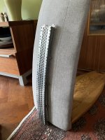
First I did a another sanity check and the measurements on the printed analogue (which I have order steel parts to match) does indeed seem to be correct. Here it is in front of the current CBT speaker which uses 2.5 inch full range drivers.

And I've been playing around with materials and thicknesses. I'm in the process of selling my stock of GRS planars but since I have an odd number of the tweeters I decided to rip one open and measure the thickness of the membrane and the width of the traces:


The traces are definently wider than the holes. The magnets and the holes are 4.5 mm wide and the traces are 6 mm wide. So 133 % of the gap. Which if we scale up to 5 mm wide magnets and gaps would be 6.7 mm.
And the membrane measurements are:
mylar: 12-15 um
alu + mylar: 30-35 um
alu: 18-20 um
I guesstimate that the mylar is aluminized and etched so no adhesive layer.
For science I also measured the xmax which was ~ 0.6 mm but since it is a tweeter that makes sense. Also, the tap they have on the outside of the inner part is really thick, 50-60 microns or so.
I also got the 3 um and 6 um mylar and I don't think 3 um is realistic to use with a corrugated membrane. It is really flimsy, doesn't hold it's shape at all.
I decided to make some membranes and compare the weights of just the mylar / kapton vs the alu vs the adhesives. My gut said that while the self adhesive aluminum is very convenient to use it is really thick and probably really heavy. Spoiler, sadly I was right...
6 um mylar, 14 um alu, spray 77 adhesive: 0.64 g

12 um mylar, 30 um aluminum with 30 um acrylic self adhesive: 1.33 g

12 um kapton, 30 um aluminum with 30 um acrylic self adhesive: 1.33 g

12 um kapton tape, 30 um aluminum, 12 um silicone adhesive: 1.24 g

Just 12 um kapton: 0.22 g

2 layers of 12 um kapton tape with 12 um silicone adhesive: 0.91 g

From which we can derive the following weights:
Mylar weight == kapton weight. Makes sense and will probably have identical efficiency and distortion.
12 um mylar / kapton = 0. 22 g
6 um mylar = 0.12 g
3 um mylar = 0.6 g
14 um alu: 0.37 g
30 um alu: 0.79 g
But the interesting part, the adhesives!
30 um acrylic adhesive from the self adhesive alu: 0.32 g
12 um silicone adhesive from the kapton tape: 0.23 g
1 layer of 3M 77 spray: 0.15 g
Based on the weights I'm leaning towards staying at 12 um mylar / kapton. If I take the 6 um membrane I made but bump the foil to 12 um it would be 0.12 g heavier, or 19%. That should correspond with a 0.75 dB efficiency loss which is managable considering it would let me use kapton and thus make the membrane a lot more durable.
And on the topic of adhesives. The self adhesive aluminum is really easy to cut and convenient to use but sadly it is really heavy, I'm leaning towards the tape or using the spray. The tape adhesive is slightly heavier but more uniformly applied so might be worth the tradeoff for the durability.
And future experiments will have to determine what aluminium thickness I use, I have 14, 20 and 30 um without adhesive I can use.
I'm also toying around with the idea of not using a solid filled plane but instead cut out hexagonal holes to reduce the weight. Say if I could reduce the filled plane weight by 50 % or so, which would increase the efficiency. And hopefully it would still be stiff enough to measure as if it was completely filled so the responsed isn't messed up like it is if I do not use a filled plane at all.
And I've been playing around with materials and thicknesses. I'm in the process of selling my stock of GRS planars but since I have an odd number of the tweeters I decided to rip one open and measure the thickness of the membrane and the width of the traces:
The traces are definently wider than the holes. The magnets and the holes are 4.5 mm wide and the traces are 6 mm wide. So 133 % of the gap. Which if we scale up to 5 mm wide magnets and gaps would be 6.7 mm.
And the membrane measurements are:
mylar: 12-15 um
alu + mylar: 30-35 um
alu: 18-20 um
I guesstimate that the mylar is aluminized and etched so no adhesive layer.
For science I also measured the xmax which was ~ 0.6 mm but since it is a tweeter that makes sense. Also, the tap they have on the outside of the inner part is really thick, 50-60 microns or so.
I also got the 3 um and 6 um mylar and I don't think 3 um is realistic to use with a corrugated membrane. It is really flimsy, doesn't hold it's shape at all.
I decided to make some membranes and compare the weights of just the mylar / kapton vs the alu vs the adhesives. My gut said that while the self adhesive aluminum is very convenient to use it is really thick and probably really heavy. Spoiler, sadly I was right...
6 um mylar, 14 um alu, spray 77 adhesive: 0.64 g
12 um mylar, 30 um aluminum with 30 um acrylic self adhesive: 1.33 g
12 um kapton, 30 um aluminum with 30 um acrylic self adhesive: 1.33 g
12 um kapton tape, 30 um aluminum, 12 um silicone adhesive: 1.24 g
Just 12 um kapton: 0.22 g
2 layers of 12 um kapton tape with 12 um silicone adhesive: 0.91 g
From which we can derive the following weights:
Mylar weight == kapton weight. Makes sense and will probably have identical efficiency and distortion.
12 um mylar / kapton = 0. 22 g
6 um mylar = 0.12 g
3 um mylar = 0.6 g
14 um alu: 0.37 g
30 um alu: 0.79 g
But the interesting part, the adhesives!
30 um acrylic adhesive from the self adhesive alu: 0.32 g
12 um silicone adhesive from the kapton tape: 0.23 g
1 layer of 3M 77 spray: 0.15 g
Based on the weights I'm leaning towards staying at 12 um mylar / kapton. If I take the 6 um membrane I made but bump the foil to 12 um it would be 0.12 g heavier, or 19%. That should correspond with a 0.75 dB efficiency loss which is managable considering it would let me use kapton and thus make the membrane a lot more durable.
And on the topic of adhesives. The self adhesive aluminum is really easy to cut and convenient to use but sadly it is really heavy, I'm leaning towards the tape or using the spray. The tape adhesive is slightly heavier but more uniformly applied so might be worth the tradeoff for the durability.
And future experiments will have to determine what aluminium thickness I use, I have 14, 20 and 30 um without adhesive I can use.
I'm also toying around with the idea of not using a solid filled plane but instead cut out hexagonal holes to reduce the weight. Say if I could reduce the filled plane weight by 50 % or so, which would increase the efficiency. And hopefully it would still be stiff enough to measure as if it was completely filled so the responsed isn't messed up like it is if I do not use a filled plane at all.
Last edited:
I am back to building on my planar!
Slow but steady progress...
I have bent all the steel pieces. I did a test fit with the 3d printed plastic side pieces but where I swap in the steel plates and worked great.
Next is to wash the plates and start gluing the magnets. I will probably glue a single piece and measure it first to ensure that I haven't ruined the response by having twice as many steel supports. Then I can start the production line and glue them all.
In case anyone is wondering: I have nuts and screws in the BOX-ALL-48 boxes. They are made for electronic components but are equally amazing at storing other things as well.
Attachments
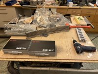
Magnets glued for a 1/6 slice of 1 speaker:
First jig to fix every second magnet

Then glue the missing magnets with the second jigs. The ca glue precision tips have worked out great. They let me apply far less glue for each magnet so there is much less overflow and glue on my fingers.


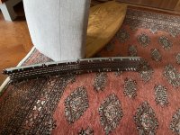
Finished magnets for the 1/6 slice. Jigs work great, the end result is great position consistency for the magnets while being easy to use.

The goal for tomorrow + monday is to cut a simple good enough membrane such that I can test run some tests and validate that everything looks good and it measures comparable to the previous experiments. The alu with the best yield has been the 30 um with the heavy 30 um acrylc glue so I will go with that.
When I have determined that it works, then the next project is to make multiple slices which will allow me to A/B test membranes instantly. I still do want to test if kapton sounds different to mylar. I also want to test if a 6 um mylar + 15 um alu sounds better than a 12 um mylar + 30 um alu, even if EQed to the same response. Handling and cutting thicker material is way easier and less prone to damage so if I can get away with thicker then I will!
First jig to fix every second magnet
Then glue the missing magnets with the second jigs. The ca glue precision tips have worked out great. They let me apply far less glue for each magnet so there is much less overflow and glue on my fingers.
Finished magnets for the 1/6 slice. Jigs work great, the end result is great position consistency for the magnets while being easy to use.
The goal for tomorrow + monday is to cut a simple good enough membrane such that I can test run some tests and validate that everything looks good and it measures comparable to the previous experiments. The alu with the best yield has been the 30 um with the heavy 30 um acrylc glue so I will go with that.
When I have determined that it works, then the next project is to make multiple slices which will allow me to A/B test membranes instantly. I still do want to test if kapton sounds different to mylar. I also want to test if a 6 um mylar + 15 um alu sounds better than a 12 um mylar + 30 um alu, even if EQed to the same response. Handling and cutting thicker material is way easier and less prone to damage so if I can get away with thicker then I will!
Unless the radiating membrane is stretching and contracting horizontally, I fail to see how the curve helps anything. Martin Logan likes to curve their panels, surely because the ignorant then think it is spreading the sound wider (plus it looks less boring than a truly flat panel). But I'd be quite shocked if the diaphragm is actually pulsing along that curve; I'm certain that in fact the entire diaphragm moves forward and backward as a unit, and the curve does not help the dispersion, which does not seem wide at all according toPhysically curved with a 75 cm radius.
https://www.stereophile.com/content...-renaissance-esl-15a-loudspeaker-measurements
https://www.stereophile.com/content/martinlogan-montis-loudspeaker-measurements
- Home
- Loudspeakers
- Planars & Exotics
- DIY midtweeter planar, physically curved and shaded to be used in a dipole CBT