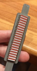
You all got me thinking so I played around with some 3d models to upload to Fractory. I tried before in FreeCad but never got anywhere but I got the idea of uploading a STEP but where the model has a realistic bend with a radius and it seems like their software is able to understand the bend in my drawing:

This is using 7 segments of 25 mm long flat sections, each bend has a radius of 2 mm.
The price in their sintant quote seems to be reasonable too, comparable to without bends even.
After I have determined if the suspension row should be open or not thus ironed down the dimensions of the driver I guess it wouldn't hurt to try and order some pre-bent laser cut parts and see how the compare. Hopefully they have a good process for bending accurately enough and then it would be perfect. And if not then at the same time I can always order non bent plates at the same time and see how it compares.
Last edited:
Hello, there is usually a specific module designed for sheet metal processes in mechanical CAD softwares because the dimentional dispesions of the creeps are dependant of the material. A plate with a chain of 500 folds with 0.05mm of creep gives 25mm of deviation on the total length.
Exactly. While I technically could order it in one piece with all the folds it is almost guaranteed to be a bad idea.
If I instead think of how many folds do I need for each segment:
Even if I only had 1 fold, it be a massive step up over no folds because of multiple reasons. I like the added stiffness of course from the bend. It would also bump the height of the steel plate to 5 cm which would let me fewer screws than it the height was 2.5 cm since I want at least 4 screws in each plate to prevent diagonal movement. Having at least one fold would also let me stagger the front and rear plates to add stiffness:

That would fix the major stiffness problems with flat planels since now the 3d printed plastic parts (black in the picture) don't need to be that strong.
It would of course be even more nice if I could have 3 folds thus bumping the plate height to 10 cm. Then we get even more overlap when staggering.
I guess I could go further to 7-8 segments but I'm not sure it would be worth it. Bigger plates will have slightly worse deviation and would be harder to force together since there are now more magnets per plate.
If I instead think of how many folds do I need for each segment:
Even if I only had 1 fold, it be a massive step up over no folds because of multiple reasons. I like the added stiffness of course from the bend. It would also bump the height of the steel plate to 5 cm which would let me fewer screws than it the height was 2.5 cm since I want at least 4 screws in each plate to prevent diagonal movement. Having at least one fold would also let me stagger the front and rear plates to add stiffness:
That would fix the major stiffness problems with flat planels since now the 3d printed plastic parts (black in the picture) don't need to be that strong.
It would of course be even more nice if I could have 3 folds thus bumping the plate height to 10 cm. Then we get even more overlap when staggering.
I guess I could go further to 7-8 segments but I'm not sure it would be worth it. Bigger plates will have slightly worse deviation and would be harder to force together since there are now more magnets per plate.
The folded plates can be easely assembled on the plastic frame if you use many small glued and superpozed segments bonded with an inexpensive GY-6010 resin.
The slow curing and high viscosity resin allows you to fully adjust the angles and the posititions of each magnets and plates on a mounting frame that simulate the magnetic gap, it will resut a perfectly regular gap with a perfect shape, the small plate tiny misalignments between themselves are technically insignifiant. The final assembly will be extremely light and stiff, i've used this process for a huge neo DIY motor and there is no problem after 10 years of intensive usage.
The slow curing and high viscosity resin allows you to fully adjust the angles and the posititions of each magnets and plates on a mounting frame that simulate the magnetic gap, it will resut a perfectly regular gap with a perfect shape, the small plate tiny misalignments between themselves are technically insignifiant. The final assembly will be extremely light and stiff, i've used this process for a huge neo DIY motor and there is no problem after 10 years of intensive usage.
Still waiting on the magnets, but hopefully they will arrive next week.
While waiting I did some more work on the membrane traces. I had first routed the traces with ExpressPCB but it got very finicky when I want to test changing the gap width between the traces, the amount of traces and so on. I got even more problems too since I can only export to PDF which I can then convert to svg but then the it generates a single line from the traces, not lines along the edges and when I tried to convert the resolution was bad.
And since I want parametric traces I went back to the tool I know so I modeled them too in cadquery and it turned out great! Here is 4 traces with 0.5 mm margin between traces:

I also wanted to test cutting with my Silhouette Cameo 5. I decided to try the Inkscape plugin https://github.com/fablabnbg/inkscape-silhouette because if I read the features correctly it can be configured to minimize backwards feeding which is useful to prevent drift across a long cutting surface.
And I got it to work! Although the Windows steps they list on the root page needed to be tweaked to work. Specifically I changed the windows commands to skip the ".\" and single quotes such that the commands I ran was:
And it works!
On my first cut experiment the result was bad. I used 50 um cutting depth on my ratchet blade, speed=10 and pressure=2.
On my second cut I slowed speed down to 2 and pressure to 1. I also changed my knife depth to 100 um. I also made such that it cuts twice, once in each direction. I also made sure to flatten the aluminum foil with the roller which I didn't do for the first cut so the surface wasn't as flat as it could have been. And it turned out great!

And pulling away the 0.5 mm gap traces wasn't a problem either, so I will continue with 0.5 mm for the gaps.
While waiting I did some more work on the membrane traces. I had first routed the traces with ExpressPCB but it got very finicky when I want to test changing the gap width between the traces, the amount of traces and so on. I got even more problems too since I can only export to PDF which I can then convert to svg but then the it generates a single line from the traces, not lines along the edges and when I tried to convert the resolution was bad.
And since I want parametric traces I went back to the tool I know so I modeled them too in cadquery and it turned out great! Here is 4 traces with 0.5 mm margin between traces:
I also wanted to test cutting with my Silhouette Cameo 5. I decided to try the Inkscape plugin https://github.com/fablabnbg/inkscape-silhouette because if I read the features correctly it can be configured to minimize backwards feeding which is useful to prevent drift across a long cutting surface.
And I got it to work! Although the Windows steps they list on the root page needed to be tweaked to work. Specifically I changed the windows commands to skip the ".\" and single quotes such that the commands I ran was:
- C:\Program Files\Inkscape\bin>python.exe get-pip.py
- C:\Program Files\Inkscape\bin>python.exe -m pip install pyusb
- C:\Program Files\Inkscape\bin>python.exe -c "import usb.core; x = usb.core.find(); print(x)"
DEVICE ID 0b4d:1140 on Bus 000 Address 001 =================
...
This command was not needed but I ran this to validate that the cutter was found correctly. And it correctly listed device 0b4d so seems to work.
And it works!
On my first cut experiment the result was bad. I used 50 um cutting depth on my ratchet blade, speed=10 and pressure=2.
On my second cut I slowed speed down to 2 and pressure to 1. I also changed my knife depth to 100 um. I also made such that it cuts twice, once in each direction. I also made sure to flatten the aluminum foil with the roller which I didn't do for the first cut so the surface wasn't as flat as it could have been. And it turned out great!
And pulling away the 0.5 mm gap traces wasn't a problem either, so I will continue with 0.5 mm for the gaps.

Great news, OllBoll!
I never got InkScape to work, so I will try it your way.
Having to connect the cutter using USB is a drawback though.
By the way, "Pulling away" is called weeding.
I never got InkScape to work, so I will try it your way.
Having to connect the cutter using USB is a drawback though.
By the way, "Pulling away" is called weeding.
Good to know!By the way, "Pulling away" is called weeding.
On the topic of the gap width between the traces. The above cuts used 0.5 mm but I think I can push it lower. But I will push those experiments to the future and stick with 0.5 mm for now since I have confirmed it to work well enough. I will also postpone experimenting with fill around the traces or empty space since using fill has worked well enough for others so should be a good enough starting point.
My next goal is to determine:
- What hole configuration should I use? I will create a flat prototype in each following configuration:
- "The standard" layout: 4 holes and traces in all holes. Suspension at the sides covered by the steel plates. Very similar to @solhaga s design.

- Holes in the plate where the suspension is. Use a suspension that isn't too restrictive such that it at least lets through low frequencies. Also route traces in all 6 holes so it is kind of like how the Neo3PDR has 3 rows of magnets but 4 rows of traces. The outermost holes will not have a magnet field as linear or as strong as the inner holes but experiments will have to show it has a significant impact on performance or not.

- Use the concept of using the output from the suspension hole but only use the 4 inner holes where the magnet field is linear. This is basically a standard layout with less width so less dipole peak and since there is now less membrane mass outside of the where sound is generated it should in theory be more efficient, as long as it doesn't generate undesirable noise which is entirely possible.

- "The standard" layout: 4 holes and traces in all holes. Suspension at the sides covered by the steel plates. Very similar to @solhaga s design.
- Can I curve the steel plate without impacting the efficiency in a significant way?
I plan to also make a curved prototype of "The standard" (1.1) layout. Then test with and see how efficiency and everything compares. If it is close enough then I will use curved plates for my design since they would be easy to manifacture. If not then I will start playing around with using flat but factory-bent steel plates.
Only when I have first answered the above open questions and decided on a setup will I continue to trim the performance by testing the among other things the following (list is in no particular order):
- Different xmax, compare 3 vs 4 mm.
- Traces width. Should I have only traces where the magnet field is the most linear or a more wide pattern also overlapping the magnet edges slightly?
- Should I have a filled plane of aluminum outside of the traces or just mylar?
- Less gap in between traces, can I go down to 0.3 mm?
- Kapton instead of Mylar, does it measure and sound different? The increased thermal ruggedness would be a huge benefit.
- Single ended setup, test only magnets on the rear.
For clarity:
In all the immediate future experiments I mention above I will use 4 mm xmax and the following membrane tracing (3 mm width across both traces):

The goal is to closely clone @solhaga s design since as per his measurements, it works and performs great thus will provide an excellent baseline.
Mine will differ slightly in that I will run 2 traces instead of 1 which he has in his experiment but should not impact performance in a significant way. I will also use a much thicker membrane than he does but I believe that should mainly reduce the efficiency on the high end but apart from that not impact the distortion spectrum or frequency response. As long as the distortion performance is comparable I.E. distortion including higher order harmonics falls off a cliff above 300 hz then I am satisfied.
In all the immediate future experiments I mention above I will use 4 mm xmax and the following membrane tracing (3 mm width across both traces):
The goal is to closely clone @solhaga s design since as per his measurements, it works and performs great thus will provide an excellent baseline.
Mine will differ slightly in that I will run 2 traces instead of 1 which he has in his experiment but should not impact performance in a significant way. I will also use a much thicker membrane than he does but I believe that should mainly reduce the efficiency on the high end but apart from that not impact the distortion spectrum or frequency response. As long as the distortion performance is comparable I.E. distortion including higher order harmonics falls off a cliff above 300 hz then I am satisfied.
Last edited:
I would think that applying a lot of force close where the membrane is suspended might be a waste and perhaps even "bad"...
//
//
I have both had great success and frustrating failure today:
I have a cut membrane on Mylar!

But the bad news is that while I got one working I had 20+ failures.
The problem is that either I hit a crease where the foil pulls up and ruin the coil or the temporary glue isn't sticky enough which releases a part which then in most cases also ruin the coil.
The success last week was with the Silhouette Cameo cutting mat, fresh from the package with fresh glue and with no prior cuts. The aluminum foil sticks extremely good to their adhesive and with no prior cuts it went great. But when I try again then the foil won't lie flush since it gets creased by the previous cuts in the mat. This causes the knife to catch on the creases and ruin the coil.
I also tried the pre applied adhesive aluminum foil but that one is a dice roll since the foil doesn't stick that well to the backing paper, far less than the sticky cutting mat so the 0.5 mm trace gaps release instantly and ruin the coil since the sticky side in most cases catch on another piece and pull it up. The coil in the image is with pre applied adhesive but where I was lucky enough that while it did release it didn't ruin the coil like the 10 other times I tried this combo.
I've also tried with 3M re mount spray glue which while it is more sticky than the pre applied adhesive adhesive paper it isn't as sticky as the cutting mat so those failed too. If I continue to use the re mount glue then it might be a good idea to wait for the glue to harden some before cutting. The specs list it is movable up to 12 hours so if I wait 6-12 hours then it should stick more.
But I might also have to bump the gap in between the traces. 0.5 mm can probably work if I can get a temporary glue that is as sticky as the fresh cutting mat but if not then I have to increase it. And this is with a 20 cm long coil without any shading in it so it is simple. If I want any chance of cutting a 2 m long coil with complex shading without guaranteeing it to be ruined it is probably a good idea to bump the safety margin by increasing the gap width.
I have a long weekend so Monday off from work and I really want to have a working prototype on Monday. I'm thinking I'll accept this membrane as good enough since I only need that one to make a solhaga clone + same setup but curved. So the plan for tomorrow is to glue all the magnets for those configurations.
If I get the magnets glued before they day is done so I have time over then I can play around some more with membrane coils. But in that cae I'll bump the trace gap to 1 mm to reduce risk of failed cut foils. I can always improve the cutting process to allow for a smaller gap in the future. Right now there are more interesting questions like:
When I have finalized what setup I want, how wide the driven trace width should be, if the outer holes where the suspension is should be open or not and so on then I can play around with improving the cutting process to allow for a reduction of gap.
I have a cut membrane on Mylar!
But the bad news is that while I got one working I had 20+ failures.
The problem is that either I hit a crease where the foil pulls up and ruin the coil or the temporary glue isn't sticky enough which releases a part which then in most cases also ruin the coil.
The success last week was with the Silhouette Cameo cutting mat, fresh from the package with fresh glue and with no prior cuts. The aluminum foil sticks extremely good to their adhesive and with no prior cuts it went great. But when I try again then the foil won't lie flush since it gets creased by the previous cuts in the mat. This causes the knife to catch on the creases and ruin the coil.
I also tried the pre applied adhesive aluminum foil but that one is a dice roll since the foil doesn't stick that well to the backing paper, far less than the sticky cutting mat so the 0.5 mm trace gaps release instantly and ruin the coil since the sticky side in most cases catch on another piece and pull it up. The coil in the image is with pre applied adhesive but where I was lucky enough that while it did release it didn't ruin the coil like the 10 other times I tried this combo.
I've also tried with 3M re mount spray glue which while it is more sticky than the pre applied adhesive adhesive paper it isn't as sticky as the cutting mat so those failed too. If I continue to use the re mount glue then it might be a good idea to wait for the glue to harden some before cutting. The specs list it is movable up to 12 hours so if I wait 6-12 hours then it should stick more.
But I might also have to bump the gap in between the traces. 0.5 mm can probably work if I can get a temporary glue that is as sticky as the fresh cutting mat but if not then I have to increase it. And this is with a 20 cm long coil without any shading in it so it is simple. If I want any chance of cutting a 2 m long coil with complex shading without guaranteeing it to be ruined it is probably a good idea to bump the safety margin by increasing the gap width.
I have a long weekend so Monday off from work and I really want to have a working prototype on Monday. I'm thinking I'll accept this membrane as good enough since I only need that one to make a solhaga clone + same setup but curved. So the plan for tomorrow is to glue all the magnets for those configurations.
If I get the magnets glued before they day is done so I have time over then I can play around some more with membrane coils. But in that cae I'll bump the trace gap to 1 mm to reduce risk of failed cut foils. I can always improve the cutting process to allow for a smaller gap in the future. Right now there are more interesting questions like:
- Should the suspension holes be open or not?
- Should the steel plates it be flat but segmented, curved or bent?
- Should the driven trace width be 3 mm or more?
- Should I stay at 2 mm xmax or is there a benefit in reducing to 3 mm?
When I have finalized what setup I want, how wide the driven trace width should be, if the outer holes where the suspension is should be open or not and so on then I can play around with improving the cutting process to allow for a reduction of gap.
Yes, the foil must be flat on the cutting carrier without any "bumps"; even a small dust grain can lift the tool so that the knife doesn't cut through and rips the foil instead.
Increasing the force on the tool might help.
Increasing the force on the tool might help.
The frame you made for tensioning the membrane is wrong.
You need a tensioning system in two planes with pressure gauges (a spring balance up to 5 kg), then you will control the pressure of each membrane and will not allow wrinkles.
Advice: in your case, you can make different tension for each segment, then each segment will have a different resonance, and this is useful.
At last we have (some) measurements! I ran out of time so I only had time to test a few combinations:
First upp is a SE variant of the solhaga setup: 2 mm xmax, 3 mm traces width & Clas Ohlson self adhesive weatherstrip as suspension:


The resistance of the membrane is 2.1 ohm. I connected a 4 ohm resistor in series to make the load on my amp easier. The measurements were indoor with a wall fairly close, I believe that the 90 degree bump at 6-10 khz will go away if I do a more proper measurement.
The efficiency, however, is not good. Since measuring the efficiency is so depedent of the baffle I decided to just compare it to a known driver instead. That driver is the GRS 6825:


It is at best 7 dB less efficient than the GRS 6825 above 500 hz, ouch. We can of course gain 3 dB by going push-pull but I'd prefer the gap to be closer than that.
Distortion compared to GRS PT6825:


The distortion is not that bad though, which is promising.
So I decided to go all in and try:


The resistance of this membrane was slightly higher at 2.4 ohms. The efficiency also is a lot higher which is nice. It is even comparable to the GRS PT6825!

But we can't have such good results without some failure, here is the distortion:

Yikes! Great above 3 khz but something is obviously wrong so I had a look around the driver and I messed up the suspension. The glue from the weatherstips caught on the magnets so the membrane was touching the magnets on one side.

Next weekend I'll try to fix this by using suspension without adhesive, or at least to apply the adhesive myself to ensure it is applied where I want it. Hopefully the fixed suspension won't negatively impact the efficiency.
I also plan to test the PDR setup + physically curved plates. I have the magnets glued to curved plates but ran out of time to measure them.
Random lessions I have learnt:
First upp is a SE variant of the solhaga setup: 2 mm xmax, 3 mm traces width & Clas Ohlson self adhesive weatherstrip as suspension:
The resistance of the membrane is 2.1 ohm. I connected a 4 ohm resistor in series to make the load on my amp easier. The measurements were indoor with a wall fairly close, I believe that the 90 degree bump at 6-10 khz will go away if I do a more proper measurement.
The efficiency, however, is not good. Since measuring the efficiency is so depedent of the baffle I decided to just compare it to a known driver instead. That driver is the GRS 6825:
It is at best 7 dB less efficient than the GRS 6825 above 500 hz, ouch. We can of course gain 3 dB by going push-pull but I'd prefer the gap to be closer than that.
Distortion compared to GRS PT6825:
The distortion is not that bad though, which is promising.
So I decided to go all in and try:
- Reduce mechanical xmax from 2 mm to 1.5 mm.
- Double membrane traces width from 3 mm to 6 mm for each magnet gap row.
- Push-pull.
The resistance of this membrane was slightly higher at 2.4 ohms. The efficiency also is a lot higher which is nice. It is even comparable to the GRS PT6825!
But we can't have such good results without some failure, here is the distortion:
Yikes! Great above 3 khz but something is obviously wrong so I had a look around the driver and I messed up the suspension. The glue from the weatherstips caught on the magnets so the membrane was touching the magnets on one side.
Next weekend I'll try to fix this by using suspension without adhesive, or at least to apply the adhesive myself to ensure it is applied where I want it. Hopefully the fixed suspension won't negatively impact the efficiency.
I also plan to test the PDR setup + physically curved plates. I have the magnets glued to curved plates but ran out of time to measure them.
Random lessions I have learnt:
- @solhaga you were right that Silhouette Studio cuts better than the Inkscape plugin. Especially in the curves. I also learned the hard way that in Silhouette Studio when you import a dxf it defaults to rescale the image to fit the cutting area...
- Those magnets are scary! I got my fingers caught in between two plates and it was really painful. To reduce the disk of accidents I have decided that there is absolutely no way I will do the whole speaker in single front + back pieces. Even 16 cm tall plates are pusing it and I will probably reduce it down to at most 10 cm, maybe even 5-8 cm. I'm thinking I'll have longer plates on the rear inner part of the driver, say 20 cm but then segment the front much more say 5 cm so they are easier to mount.
- Aluminum foil loves to rip when being cut. The small gaps also love to be self weeded and cause rips. I'm thinking of segmenting the long traces into parts to reduce the risk of them being ripped up. The last mm or so I could easily cut with a scalpel. The segmentation should also, in theory make such that when cutting the 2 m long membrane the cutter will cut each segment in order and won't roll the membrane back and forth the whole length for each cut, should reduce the risk of drift in the short axis.

Last edited:
Jag föreslår att man EQar rakt innan distortion mätningar
EQing straight is definently the way to get true comparable measurements. Would have taken more time than I had at hand though so will have to wait until next week.
I've discovered that Silhouette Studio is not complying with all DXF variants. For instance, exporting a design as DXF from Fusion can look really bad when imported to Silhouette Studio.
- @solhaga you were right that Silhouette Studio cuts better than the Inkscape plugin. Especially in the curves. I also learned the hard way that in Silhouette Studio when you import a dxf it defaults to rescale the image to fit the cutting area...
The remedy is for example to import the DXF file to a third programme, I've used FreeCAD, and then export it again.
Import that DXF file "as-is" will be alright in Silhouette Studio; you only have the move it to the right place.
Yes , the yield will be very low when cutting a two long membrane in one go.3. Aluminum foil loves to rip when being cut. The small gaps also love to be self weeded and cause rips. I'm thinking of segmenting the long traces into parts to reduce the risk of them being ripped up. The last mm or so I could easily cut with a scalpel. The segmentation should also, in theory make such that when cutting the 2 m long membrane the cutter will cut each segment in order and won't roll the membrane back and forth the whole length for each cut, should reduce the risk of drift in the short axis.
I might take you up on your idea of segments.
When I cut the 7 µm aluminium foil with the paper backing, I use auto knife set to one, force to 15 and the speed to five.
I've glued the foil to the brown paper side of milk carton as a cutting mat.
- Home
- Loudspeakers
- Planars & Exotics
- DIY midtweeter planar, physically curved and shaded to be used in a dipole CBT