Yup, there is no substitute for just building it and measuring.
To allow varying the magnet gap from 2.5 - 4mm when testing I'm thinking of elongating the holes slightly in the curved steel part. Then I should be able to swap the thickness of the plastic yellow edge part to change the gap.
I did some napkin math and the difference in hole placement of 2 vs 4 mm magnet gap is 0.5 mm on the outermost holes so I added 1 mm on all holes to be safe.

I wanted to test if the cheap rolling mill (SJ 300) I bought is strong enough to roll my 2 mm thick plates so I made a test plate:


The real plates would have more holes so the idea is that if I can curve this plate, then I should also be able to curve the actual plates with more holes.
And as it turns out, it worked great!

It worked so well I'm thinking of redesigning the speaker slightly. The plan was to make the final speaker in 8 x 20 cm segments. But one problem is how to join the segments without creating a massive weak point.
And then I realized that I don't need to segment the driver. The segmentation was just a limitation of my 3d printer since it has a 25cm3 build volume but the main strength now is from the steel and I can order 160 cm tall laser cut parts no problem. A benefit of not segmenting is that I can also add an offset to the magnets such that the gaps don't all align.
For the next tests where I want to try varying the row holes and xmax I will still order 20 cm segments but then for the final driver I would then scale upp to 160 cm tall without segments.
Next step is to determine how big the lengthwise gap between the magnets should be. I'm leaning towards 0.25 - 0.5 mm. Smaller is better of course but 0.5 mm would be easier to glue and probably good enough.
The real plates would have more holes so the idea is that if I can curve this plate, then I should also be able to curve the actual plates with more holes.
And as it turns out, it worked great!
It worked so well I'm thinking of redesigning the speaker slightly. The plan was to make the final speaker in 8 x 20 cm segments. But one problem is how to join the segments without creating a massive weak point.
And then I realized that I don't need to segment the driver. The segmentation was just a limitation of my 3d printer since it has a 25cm3 build volume but the main strength now is from the steel and I can order 160 cm tall laser cut parts no problem. A benefit of not segmenting is that I can also add an offset to the magnets such that the gaps don't all align.
For the next tests where I want to try varying the row holes and xmax I will still order 20 cm segments but then for the final driver I would then scale upp to 160 cm tall without segments.
Next step is to determine how big the lengthwise gap between the magnets should be. I'm leaning towards 0.25 - 0.5 mm. Smaller is better of course but 0.5 mm would be easier to glue and probably good enough.
I've ordered 3000 12x5x3 mm magnets & I've ordered 16 cm tall test plates of the 3 setups in post https://www.diyaudio.com/community/...o-be-used-in-a-dipole-cbt.412132/post-7719890 but with elongated holes to let me play around with xmax.
First I'll play around with the shorter plates to test layout but I also decided to order full length steel plates at the same since it wasn't that much more expensive and then I can test if my hole alignment is correct across the full 155 cm length and if the curve is right.
For the full length plates I went with the most standard setup which probably will be the best performer. So 4 mm mech xmax, 4 rows of holes and suspension covered and not exposed. Basically the standard layout for planars and identical to solhagas setup. After testing the small scale configs I'll either reorder the full length plates in the best performing config or keep the current if it turns out to be the best.
Yes, that is the plan at least.So an actual sound check is not far in the future?
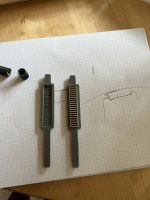
I got my test batch of magnets painted for polarity. Works well enough but I sprayed a bit thick on some so it dripped somewhat. For the rest I'll do two passes of thinner coats instead to avoid the dripping.
For the first stack I chose polarity at random. Then for each consecutive stack I resued one previously polarity painted magnet to ensure that the black part on all magnets have the same polarity. Seems to work well enough.
The next project is to make the steel plate magnet gluing jigs for the curved plates. I hope to get them done during next weekend such that they are ready for the weekend since bu then I expect the new steel plates to have arrived.
Attachments

I have had both great success, some meh and a massive disaster:
Good
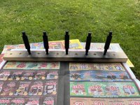
I received the steel and it turned out great!

Meh
I glued the magnets on one side and I definently need to redo my process of how I glue the magnets. They just slide on the glue so they won't stay put so it is a pain to get them to where I want them to be.


I have 2 ideas of how to remake the magnet glue jig:
Disaster
When I glued the other side I didn't wait long enough for the glue to harden. I was afraid that the glue would stick too hard to the plastic jig parts but I pulled them too early. The magnets stuck to each other and didn't stay in their rows. In the image I have pulled the offending magnets but since they wont stay aligned tight enough it is pretty much impossible to fix this by adding magnets afterwards.

So I have accepted these magnets as unsalvagable and pulled them all off the metal. The sad part is that I don't have enough magnets to redo the test piece right now. I do have more magnets on the way that might arrive next week if I am lucky but if not then by the week after next. So If I am lucky I might get working measurements by next weekend but the weekend after that is more likely.
Also: I have also learned that black is a bad color to use to signify the magnet polarity. It gets mixed up with the shadows of the metal and the magnets so it is difficult to see on what side they are colored. For the large batch of magnts I'll probably buy a can of red primer which should be a lot easier to see and solve that problem.
Good
I received the steel and it turned out great!
Meh
I glued the magnets on one side and I definently need to redo my process of how I glue the magnets. They just slide on the glue so they won't stay put so it is a pain to get them to where I want them to be.
I have 2 ideas of how to remake the magnet glue jig:
- Instead of gluing all the magnets in one go, make a jig to glue every second magnet in the row. Then add the magnet in between in a second pass. This will ensure that the gap in between the magnets is very consistent. A risk is that either I need to coat the jig in something to make it not stick to the epoxy, or print the jig in PP such that it doesn't stick, or design the jig to reduce the risk of it sticking. I also need to come up with some clever way to ensure no glue is pushed into the gap in between the magnets thus posing a problem for the remaining magnets in the second pass.
- Bump the gap in between the magnets and then print supports to hold the magnets in place and glue it to the plates with the magnets. Kind of like this
 but possibly thinner supports in between the rows. I'm also considering if the supports across the gaps should be left in place or if I should cut them off when the glue has hardened completely. A benefit with this idea is that I can glue all magnets in one go and I don't have to worry about having to remove the plastic. A potential problem, if I want to remove the middle supports across the gaps is that I'd probably need non magnetic detail cutters since the ones I have want nothing more than to stick to the magnets 😆
Disaster
When I glued the other side I didn't wait long enough for the glue to harden. I was afraid that the glue would stick too hard to the plastic jig parts but I pulled them too early. The magnets stuck to each other and didn't stay in their rows. In the image I have pulled the offending magnets but since they wont stay aligned tight enough it is pretty much impossible to fix this by adding magnets afterwards.
So I have accepted these magnets as unsalvagable and pulled them all off the metal. The sad part is that I don't have enough magnets to redo the test piece right now. I do have more magnets on the way that might arrive next week if I am lucky but if not then by the week after next. So If I am lucky I might get working measurements by next weekend but the weekend after that is more likely.
Also: I have also learned that black is a bad color to use to signify the magnet polarity. It gets mixed up with the shadows of the metal and the magnets so it is difficult to see on what side they are colored. For the large batch of magnts I'll probably buy a can of red primer which should be a lot easier to see and solve that problem.
Last edited:
While that is probably a contributor I believe it to be miniscule compared to everything else*. When I test fitted magnets without glue they stuck well enough and didn't slide around too much and twisted and sometimes connected the rows. But when I added the epoxy glue then they really liked to move. They even slid around enough that they connected in between the rows. This is what completely ruined my attempt since then I couldn't just force back the jig supports to force them back into aligntment. I probably had a too thick layer of glue but when the magnet had slid around somewhat it got thinner. But it might be worth trying a thinner runnier glue like ca glue.Normally the magnets attach to the steel enough, but as your steel plates are curved...
Apart from the glue I believe the main culprit to be that my magnets are so short. So for each lengthwise magnet gap where they repel each other there is much less magnet in contact with the steel.
*EDIT: If my mathing is correct then given a 75 cm radius and 12 mm magnets then the gap in the middle of each magnet is just 24 um, probably a lot less than how thick my glue layer will be.
Last edited:
I just realized a benefit of using ca glue instead of epoxy, which is that it is dissolvable in acetone even if hardened.
So say I make the jig where I can glue every second magnet in a first pass. Even if I accidentally splash some glue in the gap where the magnet should go in the next pass I can remove it.
So say I make the jig where I can glue every second magnet in a first pass. Even if I accidentally splash some glue in the gap where the magnet should go in the next pass I can remove it.
For science:
Given a radius of 75 cm, here are calculations of the curve error of different magnet lengths. Basically if I have a perfectly curved steel plate and place a magnet on the curve, how big is the gap in the middle (which will need to be filled by glue). Also large gaps will reduce efficiency as solhaga has shown in his simulations.
magnet_length = 6 mm
diff_mm = 0.006 mm
diff_um = 6.0 um
magnet_length = 12 mm
diff_mm = 0.024 mm
diff_um = 24.0 um
magnet_length = 25 mm
diff_mm = 0.104 mm
diff_um = 104.167 um
magnet_length = 50 mm
diff_mm = 0.417 mm
diff_um = 416.667 um
magnet_length = 100 mm
diff_mm = 1.667 mm
diff_um = 1666.667 um
With longer magnets the curve error quickly becomes significant but I think my choice of 12 mm magnets proves to be a good choice for my use case.
It doesn't matter if the gap is small and there is glue there - it's the actual contact area that governs the friction and makes it stay. Adding glue is like lubrication of course... only way to increase the friction is to not have a continue curve byt a segmented bend of the underlying metal. Probably very little glue is needed if surface is flat.
//
//
I agree with TNT.
Another thought is: do you really need the plates to be curved?
If you have segmented flat plates, a thin 3D printed curved front will make the desired curve.
It might even lower the Q of the Helmholtz resonance.
Another thought is: do you really need the plates to be curved?
If you have segmented flat plates, a thin 3D printed curved front will make the desired curve.
It might even lower the Q of the Helmholtz resonance.
For science:
magnet_length = 100 mm
diff_mm = 1.667 mm
diff_um = 1666.667 um
With longer magnets the curve error quickly becomes significant but I think my choice of 12 mm magnets proves to be a good choice for my use case.

I agree with TNT.
Another thought is: do you really need the plates to be curved?
If you have segmented flat plates, a thin 3D printed curved front will make the desired curve.
It might even lower the Q of the Helmholtz resonance.
The plates do not have to be curved, but if they are it greatly simplifies the mechanical construction. I could as you say make them segmented but then the 3d printed edge parts are what holds the driver together mechanically so they have to be a lot thicker. That adds say 8 mm to the width which in turn makes the dipole peak more of a problem. It also eats into the height available to the suspension since I then can't glue the suspension to the steel plate but rather need to attach it to the edge parts. That reduces the available suspension height of 5 mm down to 3.5 mm.
None of those problems are stoppers, they can be worked around but it would be convenient if the plates can be curved and double duty as mechanical strength to keep everything together without negatively impacting the performance.
But your reservations have made me want to try a flat plate too. I did order extra pieces and with the elongated holes I don't even have to modify them. I just have to print flat edge pieces and flat glue jigs and I'm good to go. When I get the large batch of magnets I'll probably do that.
And even if curved prove to be worse it should still be good enough for me to determine what hole configuration I want. Basically which of the setups from post https://www.diyaudio.com/community/...o-be-used-in-a-dipole-cbt.412132/post-7719890 I should use.
I'm also thinking that even if I continue with a curved plate I might split it into 20 cm tall segments instead of a single 160 cm piece. The magnets are damn strong and since I want push-pull it would be very tricky to mount the front steel plate if it is a single curved piece. I have guide rods of non magnetic stainless steel but since there is a curve I can only use one rod at each side. If the plates are smaller this is less of a problem.
Also the process of handling and gluing all the magnets would be tricky with a single 160 cm tall plate. Much easier in smaller segments.
Also the process of handling and gluing all the magnets would be tricky with a single 160 cm tall plate. Much easier in smaller segments.
In principle sure but the problem is: how would I make the bends? I don't know what tool I could use, which is within my hobbyist budget, that can make 4 * 125 bends with excellent tolerances?I mean that you should bend the iron i flat sections - one long part 🙂
//
One option would be to use a manually operator sheet metal bending machine like this:

But there are some problems:
- I'd bend 2 mm steel which is quite thick so the bends are not symmetric because only one side is bolted down in the tool. That is fixable but then I'd have to hammer down the bends and that would take a lot of time for 500 bends 😵.
- It requires a manual step where I basically eyeball where the bend should be. I can use a marker of course but in the end, will I be able to have good enough tolerances of where the bend is centered?
- Even if the bends are centered exactly where I want them to be, I don't think I'll be able to bend exactly the right amount such that all bends have the right angles.
- Too labour intensive even without hammering the bends. Lets be generous and say I can make a single bend in 3 minutes. Then that is still 25 hours of just bending, I would prefer a faster method.
If I had an unlimited budget I could get a tool steel die made and have them use a hydralic press which would get the job done but those tools are slightly out of the scope of my budget...
But if you know a tool / process for which I could make the bends on the cheap, fast enough and with excellent tolerances then I would love to know 🙂
In the end if I go with flat plates then I think the best way forward is to segment the driver into 1 or 2 magnet length plates, so 12.5 or 25 mm and then widen the 3d printed plastic part to add structural strength. Maybe also print with something stronger than plain PETG, probably some fancier and more expensive carbon fiber reinforced filament. Maybe also add a slot in the 3d printed part and glue in a flat laser cut steel sheet reinforcement. Even CF reinforced plastic is no where close to steel in strength.
Good idea with the grooves... and not one bend per magnet - do it like in 5-10cm flat segments. I think you need to depart from the absolute optimal if you want progressions ;-)
The bending "machine" needs to be shallower then the segments or you wont be able to bend it in one piece which is what I perhaps think you should do...
//
The bending "machine" needs to be shallower then the segments or you wont be able to bend it in one piece which is what I perhaps think you should do...
//
- Home
- Loudspeakers
- Planars & Exotics
- DIY midtweeter planar, physically curved and shaded to be used in a dipole CBT