Hello Calvin,
Please understand that the inclusion of an input transformer is a personal choice and is not in any way intended to be criticism of your design, which I rather like. If you read my original post, I was thinking along similar lines but never followed through. I only did the noise calculations to point out that a transformer can indeed improve tnoise, that’s all. Yes, I agree that modern head amps have noise levels well below vinyl surface noise, but i think it’s about pushing the envelope - a few dB extra headroom here, a couple of dB lower noise there.
The reason I prefer transformer coupled stages is very simple: safety. Many years ago I owned an outstanding MC cartridge, the Denon DL 1000 – few people know about it today. Back in the day it was one of several high compliance, high trackability MC cartridges made in Japan. At 1.25 g it could out track a Shure V 15 and it had extended bandwidth to well beyond 20 kHz. A very good friend of mine borrowed it - FWIW, I would not loan out a cartridge today - and burnt it out when his brand new audiophile approved valve preamp sent a turn-on transient through the cartridge. Now, it takes a great deal of talent to design a valve preamp that’ll do that, but that’s neither here nor there. Also, I know of another audiophile who had a multi k$ Ortofon MC cartridge wiped out by an esoteric head amp. So these days I lean towards transformer coupled MC stages.
So there you have it - safety first, that’s all.
Edit: A well made transformer can be very good indeed. See the Jensen data sheet on the 346 and 347.
https://www.jensen-transformers.com/transformers/moving-coil/
Last edited:
Hi,
You´re right, its a personal choice and galvanic isolation is one of the few reasons in favour of a SUT.
On the other hand one could use coupling caps in the INAs input lines. 😉
jauu
Calvin
You´re right, its a personal choice and galvanic isolation is one of the few reasons in favour of a SUT.
On the other hand one could use coupling caps in the INAs input lines. 😉
jauu
Calvin
My test LP arrived in town, but is not with me yet, tomorrow I can show some progress with it.
Today I run something that can change picture on one subject: overload margin.
Personally I believed in it all the time, now I measured, and it confirms with small test.
Test song is Strange Angels from Laurie Anderson, 1st from A side. This LP (original Warner Bros issue from 1989) I bought new at time of issue and is being played a lot, it's not a perfect LP by any means, but not worst neither. In any case I choose this as it is somewhere in the middle between new audiophile records and overused - misused scrap, this LP is kind of thing we like to play, glorious music of choice but not an audiophile record.
On the picture below are one song peaks recorded from beginning to an empty end, including stylus being placed and removed.
Red: measured straight at points A and B (post #399 above), just x 1000 x 2 gain of first phono stage
Green : final signal after complete preamp (added passive Riaa + 20db gain), ready to listen

What I want to say with this little test is: even there is x1000 x 2 gain (2x ssm2017 with gain of x1000 in opposite polarity) , there is still no way to reach overload in HF region whatsoever.
Soon I will run the same with different variety of LP's to confirm, but Im kind of sure that x1000 or 60db gain directly after MC cart with 0.xx mV output will do no harm, instead just improve SNR of total system
Today I run something that can change picture on one subject: overload margin.
Personally I believed in it all the time, now I measured, and it confirms with small test.
Test song is Strange Angels from Laurie Anderson, 1st from A side. This LP (original Warner Bros issue from 1989) I bought new at time of issue and is being played a lot, it's not a perfect LP by any means, but not worst neither. In any case I choose this as it is somewhere in the middle between new audiophile records and overused - misused scrap, this LP is kind of thing we like to play, glorious music of choice but not an audiophile record.
On the picture below are one song peaks recorded from beginning to an empty end, including stylus being placed and removed.
Red: measured straight at points A and B (post #399 above), just x 1000 x 2 gain of first phono stage
Green : final signal after complete preamp (added passive Riaa + 20db gain), ready to listen
What I want to say with this little test is: even there is x1000 x 2 gain (2x ssm2017 with gain of x1000 in opposite polarity) , there is still no way to reach overload in HF region whatsoever.
Soon I will run the same with different variety of LP's to confirm, but Im kind of sure that x1000 or 60db gain directly after MC cart with 0.xx mV output will do no harm, instead just improve SNR of total system
Attachments

Please let me know what record should I play and capture highest possible HF signal before RIAA attenuation, which one has highest HF recorded?
I will do if I or my friends have it....
I will do if I or my friends have it....
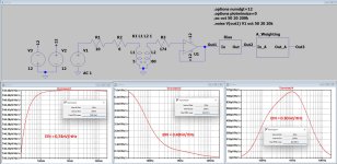
As promised, I've simulated a 1nV/rtHz and 2pA/rtHz op-amp with and without SUT with a turns ratio of 4.
For both I have shown the noise spectrum at 1) the op-amp's output, 2) after Riaa conversion and 3) after A_Weighting.
I also have calculated the equivalent input noise, which is in case of a phono preamp the (cumulated noise from 20Hz to 20KHz)/Sqrt(20,000Hz).
My previous computation was pretty accurate, proving that only the 174R is prone to the op-amp's noise current.
So when only the input op-amp is producing noise and what comes hereafter doesn't add any additional noise, a 0.3mV Cart at 5cm/sec@1Khz, will have a S/N of 20*log(0.3mV/61.5nV) = 73.8dB-A
For the SUT version this will be 20*log(0.3mV/42.4nV) = 77.0dB-A
Hans
Attachments

The 14R Coil is looking into two transistor resistance of Rbb+1/2S.Something I am wondering about Hans. I am in the process of constructing a fully balanced "current mode" MC preamplifier that uses the SSM2212 for the differential input pair, this in lieu of using a pair of ZTX851's.
The thermal tracking proved problematic even with DC servo feedback using the ZTX devices (In contrast using the SSM2212 questions if the DC servo is even needed). The input network looks as per the following with about 1.8mA per leg. The resistors are 0.1 % to support fine tuning.
View attachment 1365396
https://www.analog.com/media/en/technical-documentation/data-sheets/SSM2212.pdf
Besides the noise "seeming" good on an oscilloscope... what would you expect the noise to be in this "current mode" application, given a Denon 103R with 0.3mV and coil resistance of 14 Ohms? It seems the noise would be dominated by the SSM2212, though it isn't clear when operating in current mode. What significance does the 2x emitter resistances have across the coil? For example what if the coil resistance was 0 Ohms?
With 1.8mA, 1/2S is ca 7R, but I don't know the SSM's Rbb
For the ZTX it is ca 1.5R, which would add up to 2x(1.5+7) = 17R.
Together with your Cart this would become 31R or 0.72nV/rtHz.
For the SSM I would guess twice as much.
One question, why does a servo not give the expected tracking ?
Hans
Thanks Hans. The SSM parts Rbb is mentioned as 28 Ohms "typically" on the first page of the data sheet, hence adding 56 Ohms in series?
I shouldn't have suggested that it doesn't track, rather I am not keen on the movement observed caused by thermals around 0 volts that subsequent networks need to handle to further clear the sub-sonics. It seems likely that if the ZTX devices were glued together and commonly encapsulated this wouldn't be much of a problem.
One issue that seems unlikely to be a problem from your earlier dialog in another thread Hans, is the net current flow in the coils caused by mismatched transistors when the bases are tied together. Not that it can affect the sonics, I nevertheless added a 10 Ohm trimmer on the negative lower side of the 3K resistors (not shown below) to allow trimming of the emitter voltages to equality. Although the current balance is upset to some minor degree the potential difference at the collectors is zeroed at the collectors by the upper trimmer.

Of note in this network is that when all resistors are equal (in this case 3K Ohms) with equal +/- supplies, the potential at the collectors is approx. equal to the emitter voltage in the opposing direction or about +0.6 volts. Meaning that the operating voltage drop across the devices is limited to about 1.2 volts for thermal considerations, potentially leading to lower thermal drift. I didn't try this network with the ZTX's though.
A separate comment on measuring coil resistances. I am hesitant to do this myself unless with great care. A meter on the wrong resistance scale can burn out a coil. Better to use a high value series resistance that limits the current and use a voltmeter on a sensitive scale to measure the voltage drop across the coil. Keep the current under 1 mA.
I shouldn't have suggested that it doesn't track, rather I am not keen on the movement observed caused by thermals around 0 volts that subsequent networks need to handle to further clear the sub-sonics. It seems likely that if the ZTX devices were glued together and commonly encapsulated this wouldn't be much of a problem.
One issue that seems unlikely to be a problem from your earlier dialog in another thread Hans, is the net current flow in the coils caused by mismatched transistors when the bases are tied together. Not that it can affect the sonics, I nevertheless added a 10 Ohm trimmer on the negative lower side of the 3K resistors (not shown below) to allow trimming of the emitter voltages to equality. Although the current balance is upset to some minor degree the potential difference at the collectors is zeroed at the collectors by the upper trimmer.
Of note in this network is that when all resistors are equal (in this case 3K Ohms) with equal +/- supplies, the potential at the collectors is approx. equal to the emitter voltage in the opposing direction or about +0.6 volts. Meaning that the operating voltage drop across the devices is limited to about 1.2 volts for thermal considerations, potentially leading to lower thermal drift. I didn't try this network with the ZTX's though.
A separate comment on measuring coil resistances. I am hesitant to do this myself unless with great care. A meter on the wrong resistance scale can burn out a coil. Better to use a high value series resistance that limits the current and use a voltmeter on a sensitive scale to measure the voltage drop across the coil. Keep the current under 1 mA.

I would try to keep the current at ca. 0.1mA, that’s perfectly safe.Better to use a high value series resistance that limits the current and use a voltmeter on a sensitive scale to measure the voltage drop across the coil. Keep the current under 1 mA.
Hans
Hi, on this subject, I had similar dilemma. I have 2 multi meters and i connected them together; common to common and V to V. Result is that one is using approx 600mV to measure resistance, another 400mV DC.A separate comment on measuring coil resistances. I am hesitant to do this myself unless with great care. A meter on the wrong resistance scale can burn out a coil. Better to use a high value series resistance that limits the current and use a voltmeter on a sensitive scale to measure the voltage drop across the coil. Keep the current under 1 mA.
I used lover V one to measure coil. With my 40ohm cart that was 10mA DC shock for few seconds.
It all went well, coils are ok.
Nevertheless this is absolutely valuable question, what is actually coil Z, how is it dependent on frequency, and how to measure all that??? Particularly with trans impedance amps this will matter a lot...
In order to test an LP system I sometimes avoid using records with bar codes... Bar codes began being used on LP's in the early 80's... coincidentally this was about the dawning of the age of CD digital death according to Doug Sax of Sheffield labs... To some bar codes are aesthetically unpleasing... perhaps like endless lines of wind turbines along a highway... turning like dripping water torture destroying the serenity of a landscape... or works of cover art on records.Test song is Strange Angels from Laurie Anderson, 1st from A side. This LP (original Warner Bros issue from 1989) I bought new at time of issue and is being played a lot, it's not a perfect LP by any means, but not worst neither. In any case I choose this as it is somewhere in the middle between new audiophile records and overused - misused scrap, this LP is kind of thing we like to play, glorious music of choice but not an audiophile record.
I am also a fan of Laurie Anderson and use "O Superman" from Big Science as a test for dynamic range, 1st on B side (Warner Bros issue from 1982 (without the bar code)). Apparently the vocals were recorded on a Roland VP-330 Vocoder Plus in her hallway in her apartment. The tunes anchor is a gated loop transient of Laurie’s laughter in apparently an eighth-note cadence. This vocal beat can overload some preamps and has done on some of mine.
In response to: "Nevertheless this is absolutely valuable question, what is actually coil Z, how is it dependent on frequency, and how to measure all that??? Particularly with trans impedance amps this will matter a lot..."

This was tested using the above network Drbulj. For a square wave signal fed into one side of the differential pair the output was a square wave well out into the 100's of kHz. The coil behaved as a pure resistance even with a balanced interconnect cable attached to the turntable. If the coil had significant inductance or was capacitively loaded the response would changed from seemingly ruler flat. There seems no issue at all. By the way I have left the resistive divider network in for test purposes.
The barcode is about the date of manufacture, not when the master was cut, nor does it tell you how many mothers have been created from the master. Nor does it tell you who did the master cut - this is something to look up. Check the stamping numbers on the disc, I believe these can provide information on number of the mother. Do you find zebras aesthetically unpleasing?!
🙂 if something needs to be disliked, I agree, something needs to be, but why zebra? So nice animal, not horse, not donkey.... And then so useful when on the road. Might be to find something more worth disliking to satisfy that legitimate need 🙂In order to test an LP system I sometimes avoid using records with bar codes...
I love your little essays nevertheless!
Thank you!This was tested using the above network Drbulj. For a square wave signal fed into one side of the differential pair the output was a square wave well out into the 100's of kHz. The coil behaved as a pure resistance even with a balanced interconnect cable attached to the turntable. If the coil had significant inductance or was capacitively loaded the response would changed from seemingly ruler flat. There seems no issue at all. By the way I have left the resistive divider network in for test purposes.
Now the testing becomes really enjoyable, not only trying solutions, but listening to good music too. Never before I used my Sonus Fabers as near-field, I should have, they are just fantastic at 0,5m distance.
Coming back to headroom testing, I played another 3 records and recorded peaks after 2 x 60db gain and before RIAA.
Music played was :
1. O Superman, Laurie Anderson. (purple trace) @Hierfi , unfortunately I don't have original Big Science, but I do have United States live, 5 LP package. O Superman is from there
2. Notorious Telerac 1812 by Tchaikovsky (red trace), real cannons and real bells!
3. Der Rauber und Der Printz by DAF (green trace), This is little bit of electronic on EP at 45rpm

And traces:

Please note we are not coming even close to 1 V RMS and this amplifier is fully balanced; each + and - leg can easily deliver say 8 V RMS giving total of say 16V.
What clipping? What exactly one needs to play in order to clip preamp? Particularly in HF region, max signal at 10kHz was 55mV (bells from 1812)
Please let me know what you think about it, for me so far it looks that overload margin myth is busted 🙂
Coming back to headroom testing, I played another 3 records and recorded peaks after 2 x 60db gain and before RIAA.
Music played was :
1. O Superman, Laurie Anderson. (purple trace) @Hierfi , unfortunately I don't have original Big Science, but I do have United States live, 5 LP package. O Superman is from there
2. Notorious Telerac 1812 by Tchaikovsky (red trace), real cannons and real bells!
3. Der Rauber und Der Printz by DAF (green trace), This is little bit of electronic on EP at 45rpm
And traces:
Please note we are not coming even close to 1 V RMS and this amplifier is fully balanced; each + and - leg can easily deliver say 8 V RMS giving total of say 16V.
What clipping? What exactly one needs to play in order to clip preamp? Particularly in HF region, max signal at 10kHz was 55mV (bells from 1812)
Please let me know what you think about it, for me so far it looks that overload margin myth is busted 🙂
Drbulj,
I probably missed it, but could you please repeat what exactly the spectra are showing.
Is it the average sound level over some recording time or is it the maximum level that was recorded.
And what is the bin width of your filters.
When too large, the peaks may well drown in the other content also falling in this filter bin.
So I would suggest to use a filter bin of 1 Hz.
Hans
The barcode is about the date of manufacture, not when the master was cut, nor does it tell you how many mothers have been created from the master. Nor does it tell you who did the master cut - this is something to look up. Check the stamping numbers on the disc, I believe these can provide information on number of the mother. Do you find zebras aesthetically unpleasing?!
Prior to the 16th century "stripes" were considered diabolical. I suspect the devil painted the stripes on some innocent ponies... so zebras seem the devils work... as aesthetically pleasing as god himself could have done... its their eyes and teeth that scare me...
Hello Hans,Drbulj,
I probably missed it, but could you please repeat what exactly the spectra are showing.
Is it the average sound level over some recording time or is it the maximum level that was recorded.
And what is the bin width of your filters.
When too large, the peaks may well drown in the other content also falling in this filter bin.
So I would suggest to use a filter bin of 1 Hz.
Hans
Traces are maximum recorded sound levels in the course of recording, peaks.
In REW I couldn't set bin width directly, but via FFT, this is explanation from REW site:
FFT Length
The FFT Length determines the basic frequency resolution of the analyser, which is sample rate divided by FFT length. The shortest FFT is 8,192 (often abbreviated as 8k) which is also the length of the blocks of input data that are fed to the analyser. An 8k FFT has a frequency resolution of approximately 6Hz for data sampled at 48kHz. As the FFT length is increased the analyser starts to overlap its FFTs, calculating a new FFT for every block of input data. The degree of overlap is 50% for 16k, 75% for 32k, 87.5% for 64k and 93.75% for 128k. The overlap ensures that spectral details are not missed when a Window is applied to the data. The maximum overlap allowed can be limited using the Max Overlap control below to reduce processor loading at higher FFT lengths.I recorded with 192 kHz ADC resolution, and original post was 512 FFT. Here is picture of captured peaks at 16, 256 and 512 FFT. The LP is notorious Tchaikovsky Telerac with live bells and cannons. It changes, but doesn't change the point I think, we are still not close to even 1 V RMS
Sorry, but I'm a bit lost.
What exactly is a 16, 256 and 512FFT ?
When the bin width is getting larger, the lines are becoming more fluid as in your blue spectrum, but what I don't get is why the orange peaks with a smaller bin width aren't peeping above the blue spectrum or be at least equal in amplitude.
When having a single tone, the level in the spectrum remains the same, independent of bin width.
I don't see that in your spectra.
I find it a bit hard to believe that Karlov and Happ, working for Sure at the time were so wrong in their analysis.
Hans
Drbullj,
Could you apply a ca. 0.3mV 1khz tone to your amp and process this the same 3x way as the spectra in #417.
Hans
Could you apply a ca. 0.3mV 1khz tone to your amp and process this the same 3x way as the spectra in #417.
Hans
The cannon shots on the Telarc overloaded the digital recording as I recall. This doesn't follow that the LP would be cut at high levels, though it seems Telarc would record it this way in order to capture and highlight the wide dynamic range of the digital process, a process they were selling.Music played was :
1. O Superman, Laurie Anderson. (purple trace) @Hierfi , unfortunately I don't have original Big Science, but I do have United States live, 5 LP package. O Superman is from there
2. Notorious Telerac 1812 by Tchaikovsky (red trace), real cannons and real bells!
3. Der Rauber und Der Printz by DAF (green trace), This is little bit of electronic on EP at 45rpm
Maximizing the undistorted signal to noise ratio seems the primary issue. A cannon shot... or alternatively allowing for the near field recording of a nuclear weapon going off... wouldn't leave much room to record normal signals above the noise floor... if the recorder hasn't taken up smoking in its near field response. Increasing the undistorted signal headroom reduces the signal to noise ratio of lower level signals that may be sonically impacted as a result. Fidelity is about resolving harmonic structures, vocal inflections and other characteristics reliant upon resolving low level signals either in absence of noise, or being able to hear through it. Allowing for anomalies such as cannon shots can deteriorate the sonic virtues of all else being listened to. Some overloads ought to be ignored... particularly on records never played for any sonic enjoyment.
- Home
- Source & Line
- Analogue Source
- Fully balanced MC phono preamplifier thoughts