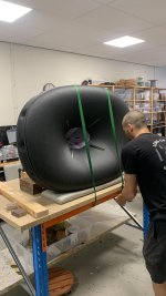
This is actualy quite nice. Gluing them with a CA (i.e. a fast) glue one by one basically let all the errors accumulate for the very last joint, which can then be quite problematic. That it was even possible what you show, means you have a pretty accurate printer, IMO.
The two sides of each petal should ideally be only rotated with respect to each other, but this seldom happens - they can be also twisted, skewed, whatever the error is. When glued like this, each joint may appear nice and accurate, until the very last one 🙂
With a slow, gap filling glue this error can be distributed among the joins more evenly. One simply assembles the full circle and let it do what it needs.
Last edited:
Could there be a support for stringing all 6 petals together when using slow glue? I'm thinking a small circle hole on the back where a piece of string could tie all petals and when applying a force where the 2 ends meet, it would squeeze the petals with equal force to all joints while the glue if setting...? Something along this line... or a snap joint integrated to the petal itself - like a ridge on one side and a hinge on the other...? click , click, click....
//
//
I'm not sure it's so easy, it would need to push evenly so that there would be no axial forces. I think just a tape should do, if necessary at all. These are not construction parts that would need to withstand any significant forces...
Very cool. Is the width (not thickness) of the spline less than the cavity? I'm just worried about a scenario where the two edges of the petal can't perfectly butt together due to the width of the spline. We surely want some wiggle room in there. To say it differently, if the cavity is 5mm deep on each side of the petal, we would want the spline to be 9mm wide. This is a different adjustment than the thickness of the spline, which want to be as close to perfect as possible.A quick spline test - 100 μm face offset is fine, I could probably do with 75 μm with some sanding.
View attachment 1364587
There's plenty of space:

(BTW, in slicers it's possible to scale the spline in width arbitrarily, if desired.)
(BTW, in slicers it's possible to scale the spline in width arbitrarily, if desired.)
Now that I've started the print - I do think the spline method is torturous on the printer. The thin walls at the beginning require quick/abrupt/short movements. I always watch the first few layers of the print. I'm still going to try it -- but just comparing it to the pinhole alignment, this is definitely more torture on the printer. I don't know if further reducing the thickness of the spline would help (e.g. 2mm think spline). Maybe these printers are more rebust than I think they actually are 🙂.
@mabat - do you have a version of the kit with the pinholes alignment system, but the modification discussed in post #15,728?
@mabat - do you have a version of the kit with the pinholes alignment system, but the modification discussed in post #15,728?
So, mind telling what you actually did with this parameter? 🙂I cannot tell you guys how much time I wasted on this goofy parameter.
...
Nothing worked. Turned out it was "Mesh.SubdomainSlices"
This really shouldn't be a problem and I would strongly recommned to decrease max. acceleration limits in your slicer if the printer is obviously suffering. All the movements should be easy, nice and smooth, without any shaking. I use 1000 mm/s^2 in X/Y with my good old Ender (running Klipper). You can keep the speed limit but decrease the acceleration.Now that I've started the print - I do think the spline method is torturous on the printer. The thin walls at the beginning require quick/abrupt/short movements
Last edited:
Far from perfect, not a disaster. The latest version of the kit must be a lot easier to get right.


(The sides of the small triangular pieces are still to be glued/bended with a bit of force, after everything else cures. Those were really the most annoying parts.)
(The sides of the small triangular pieces are still to be glued/bended with a bit of force, after everything else cures. Those were really the most annoying parts.)
Last edited:
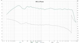
Couldn't resist, this is the FR of the unfinished one, with small gaps still all over the place.

I expect it to be smoother when finished. This would be a shame 🙂
I expect it to be smoother when finished. This would be a shame 🙂
Lightweight foaming PLA is potentially interesting, that it has open porous surface (after sanding).
PVA white glue is a decent option for coating polystyrene boards for DML panels, would be kind of fun to try it on lightweight PLA, as an alternative to coating with epoxy.
This paper discusses a PVA based compound for vibration damping https://www.researchgate.net/public...tes_by_electron_beam_processing_of_the_filler
It's more a study of the change of chemistry of the graphite after processing, but has some data on the baseline compound, it's 40% PVA, 40% graphite powder, 7% and 13% plasticizer and fire retardant.
Though I'd guess this compound is meant to be applied thickly, not sure what one would expect from just from light coating, but even if would just look good as a surface finish that would be also cool. Or adding say talcum powder, titanium oxide for nice white color components probably wouldn't hurt. (I image also pore filling.) The leftover could go onto driver diaphragms. 🙂
To fill out a WG inside maybe could try 2 component mold making silicone, there are some with density around1g/cm3, again as an alternative to epoxy.
You can as well set the 'bottom fill pattern' to 'concentric' and get rid of the short movements.The thin walls at the beginning require quick/abrupt/short movements.
This is one of the few parameters I change regularly, depending on the printed shape.
Nicely done, sir!Couldn't resist, this is the FR of the unfinished one, with small gaps still all over the place.
View attachment 1364644
I expect it to be smoother when finished. This would be a shame 🙂
That is pretty smooth as is. I don't know how much it would improve from here after filling the gaps. From your pictures posted earlier, that looks like a pretty clean assembly as is. I believe many of the cracks/openings will be invisible to the sound waves. That's my 2 cents, but what do I know 🙂.
Beautiful! Can I ask what glue you used?Far from perfect, not a disaster. The latest version of the kit must be a lot easier to get right.
View attachment 1364637 View attachment 1364638
(The sides of the small triangular pieces are still to be glued/bended with a bit of force, after everything else cures. Those were really the most annoying parts.)
It must get cleaner (and I believe it will), especially in the midrange, otherwise I wouldn't be satisfied with this. 🙂
Here's a comparison with the A520G2+STD3 (levels not matched):

Here's a comparison with the A520G2+STD3 (levels not matched):
Generally, pretty good match between your measurements (RED) vs mine (BLUE) --- considering we have different measurement setups (sound card, mic, etc.), same model - but still different drivers, different horn assembly results:Couldn't resist, this is the FR of the unfinished one, with small gaps still all over the place.
View attachment 1364644
I expect it to be smoother when finished. This would be a shame 🙂
- Home
- Loudspeakers
- Multi-Way
- Acoustic Horn Design – The Easy Way (Ath4)


