Most of the old tube testers didn't bother to get to filtered DC for their test voltages. So listening in would have been BUZZ........
Yes! This is where I'm headed when I say "overlay boards", 'topology", 'circuit types" in my previous posts. But for the novice or student, the wiring complexity is in the banana-jacked board with its schematic actually drawn on it. They just wire it with the tube of interest and measure away. Or at an advanced stage chain them up into multi stagezs
I've been breadboarding for over 70 years, mostly as a designer and troubleshooter of low-level, 24-30 bit-equivalent precision AC and DC, audio-bandwidth analog, A/D and D/A hardware for medical scanners and patient monitoring.
I love the smell of crispy-crittered ICs in the morning.
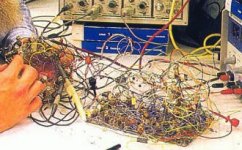
Most of my home breadboards, whether thru-hole or SMT, start out nice and neat and some end up a 3D pile of components, but not quite as bad as the attached circuit by analog giant and fellow National Semiconductor EE, the late, great Bob Pease.
1) I've been working on some high gain infrasonic audio with a low end -3dB frequency of ~ 10 milliHz for several years. My recent first use of a pegboard confirmed what I've suspected all along - pegboards are too open and mechanically unstable for microvolt-level circuits. Solder everything together or make/buy a PCB.
2) Without shielding, high gain infrasonic circuitry is sensitive enough to respond to an ESD-charged garment or charged small poly crate from at least 3 ft away.
3) I've gone through all sorts of typical protection to prevent insidious ESD damage to my breadbord's ICs - wrist staps, humidifiers and the like. I've recently found something that works well to protect them - Home Depot's Husky 18 x 100 inch black DCT130001 tool box drawer liner, ~ $18 per roll.
Just lay an 18 x 18 sheet on your bench. Stay away from adhesive-backed liner. It may make you feel more secure to lay some grounded heavy-duty Aluminum foil under the mat. It has enough carbon black to squelch ESD, but its resistance is in the 1000's of MegOhms per square, high enough to not bother live low voltage circuits. Plus, it's 1/16 inch thick and rubbery, in case you crop a component on it. Just try to avoid dropping solder blobs on it. Molten solder will embed itself.
I love the smell of crispy-crittered ICs in the morning.
Most of my home breadboards, whether thru-hole or SMT, start out nice and neat and some end up a 3D pile of components, but not quite as bad as the attached circuit by analog giant and fellow National Semiconductor EE, the late, great Bob Pease.
1) I've been working on some high gain infrasonic audio with a low end -3dB frequency of ~ 10 milliHz for several years. My recent first use of a pegboard confirmed what I've suspected all along - pegboards are too open and mechanically unstable for microvolt-level circuits. Solder everything together or make/buy a PCB.
2) Without shielding, high gain infrasonic circuitry is sensitive enough to respond to an ESD-charged garment or charged small poly crate from at least 3 ft away.
3) I've gone through all sorts of typical protection to prevent insidious ESD damage to my breadbord's ICs - wrist staps, humidifiers and the like. I've recently found something that works well to protect them - Home Depot's Husky 18 x 100 inch black DCT130001 tool box drawer liner, ~ $18 per roll.
Just lay an 18 x 18 sheet on your bench. Stay away from adhesive-backed liner. It may make you feel more secure to lay some grounded heavy-duty Aluminum foil under the mat. It has enough carbon black to squelch ESD, but its resistance is in the 1000's of MegOhms per square, high enough to not bother live low voltage circuits. Plus, it's 1/16 inch thick and rubbery, in case you crop a component on it. Just try to avoid dropping solder blobs on it. Molten solder will embed itself.
Attachments
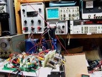
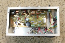
This tube tester was built from an old amp. It's results are much more reliable than any of the commercial tube testers I have:
https://www.russoldradios.com/blog/testingmatching-audio-output-tubes
https://www.russoldradios.com/blog/testingmatching-audio-output-tubes
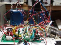
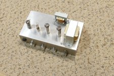
I had been making SSE amps for some time and often tried random different tubes in it. The 6EZ5 appeared on the dollar list one day, and it looked like it might be useful, so I got some. It worked well in the SSE. Sometime later I found a web site that told me a 6LU8 or 6LR8 was a 12AT7 triode and a 6EZ5 in the same bottle. This meant that the 6LR8 could be used to make a baby SSE. How do I find out if it will work in the shortest possible amount of time. Forget breadboards, why not clip leads? "That won't work!"
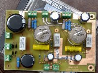
Yes, this amp actually worked, so I made a PCB from the mess. It's still around here somewhere. Don't try this with high Gm tubes, it really won't work.
Yes, this amp actually worked, so I made a PCB from the mess. It's still around here somewhere. Don't try this with high Gm tubes, it really won't work.
Attachments


I've been breadboarding for over 70 years, mostly as a designer and troubleshooter of low-level, 24-30 bit-equivalent precision AC and DC, audio-bandwidth analog, A/D and D/A hardware for medical scanners and patient monitoring.
I love the smell of crispy-crittered ICs in the morning.
Most of my home breadboards, whether thru-hole or SMT, start out nice and neat and some end up a 3D pile of components, but not quite as bad as the attached circuit by analog giant and fellow National Semiconductor EE, the late, great Bob Pease.
1) I've been working on some high gain infrasonic audio with a low end -3dB frequency of ~ 10 milliHz for several years. My recent first use of a pegboard confirmed what I've suspected all along - pegboards are too open and mechanically unstable for microvolt-level circuits. Solder everything together or make/buy a PCB.
2) Without shielding, high gain infrasonic circuitry is sensitive enough to respond to an ESD-charged garment or charged small poly crate from at least 3 ft away.
3) I've gone through all sorts of typical protection to prevent insidious ESD damage to my breadbord's ICs - wrist staps, humidifiers and the like. I've recently found something that works well to protect them - Home Depot's Husky 18 x 100 inch black DCT130001 tool box drawer liner, ~ $18 per roll.
Just lay an 18 x 18 sheet on your bench. Stay away from adhesive-backed liner. It may make you feel more secure to lay some grounded heavy-duty Aluminum foil under the mat. It has enough carbon black to squelch ESD, but its resistance is in the 1000's of MegOhms per square, high enough to not bother live low voltage circuits. Plus, it's 1/16 inch thick and rubbery, in case you crop a component on it. Just try to avoid dropping solder blobs on it. Molten solder will embed itself.
Instead of using what was in my garage, I should have been looking online for silicone ESD-reducing solder pads. They don't melt from dropped solder blobs, like I did as a 10 year old.
I couldn't wait to dress, so I was soldering in my Jockey shorts with a blunderbuss, 250 Watt iron. A huge blob of solder dropped from the iron and left very painful burns on the inside of both thighs. The scars are there to remind me. I had to explain them to my late wife, 63 years ago and to my recent online dates.
Another time, I left that same iron on, overnight, sitting on a metal bench in my parent's kitchen. It somehow rolled off and melted a huge crater in the linoleum floor. Fortunately, it didn't burn our apartment building down.
I've been breadboarding for over 70 years, mostly as a designer and troubleshooter of low-level, 24-30 bit-equivalent precision AC and DC, audio-bandwidth analog, A/D and D/A hardware for medical scanners and patient monitoring.
I love the smell of crispy-crittered ICs in the morning.
Most of my home breadboards, whether thru-hole or SMT, start out nice and neat and some end up a 3D pile of components, but not quite as bad as the attached circuit by analog giant and fellow National Semiconductor EE, the late, great Bob Pease.
1) I've been working on some high gain infrasonic audio with a low end -3dB frequency of ~ 10 milliHz for several years. My recent first use of a pegboard confirmed what I've suspected all along - pegboards are too open and mechanically unstable for microvolt-level circuits. Solder everything together or make/buy a PCB.
2) Without shielding, high gain infrasonic circuitry is sensitive enough to respond to an ESD-charged garment or charged small poly crate from at least 3 ft away.
3) I've gone through all sorts of typical protection to prevent insidious ESD damage to my breadbord's ICs - wrist staps, humidifiers and the like. I've recently found something that works well to protect them - Home Depot's Husky 18 x 100 inch black DCT130001 tool box drawer liner, ~ $18 per roll.
How many people here are even old enough to know what a CK722 is, let alone remember blowing some up. For those about to Google they were little black cubes with a red dot, made by Raytheon.
As I stated earlier my first breadboards were made with brass furniture tacks and screws, some tube sockets, and maybe a terminal strip or two scavenged from a dead radio or TV starting in the mid 60's.
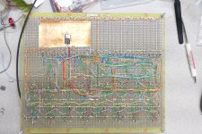
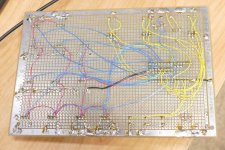
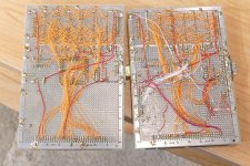
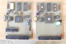
By the 1970's I built HiFi and guitar amps, crude electro-musical devices, and even simple computers that could beep out a tune or two. The pictures show a pair of 8 bit CPU boards created on perf boards with wire wrap wire and a soldering iron. I made these in the mid 90's. The board with the windowed part contained a Motorola processor chip that was never released. It would have been one of the most powerful 8 bit chips available in the mid 90's but the MC68000 16 bit chip that powered the original McIntosh computers stole its thunder.....and its spot in the wafer fab que.
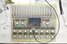
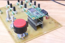
I still build stuff with the same breadboarding technique. The board with the big red knob is a simple "virtual analog" music synthesizer. I find the words "virtual analog" right up there with "Vegan Leather." The board with the slide pots, LCD touch screen, and 19 rotary encoders is part of a not so simple synthesizer with both analog and digital signal paths). This board is just the UI. The sound generator is on another equally large breadboard, still unfinished.
The latest breadboard is the vacuum tube gain stage seen in post numbers 110, 113, 114, and 119 of this thread. It uses much cheaper perf boards from Amazon.
Sometimes I make a PC board, then hack it up Pease style, then trace out what I did to make it work, then make another and put it in a real case.
Attachments
-
 P4020864.JPG427.7 KB · Views: 56
 -
 P4020861.JPG442.9 KB · Views: 63
 -
 P3990540.JPG842.2 KB · Views: 62
 -
 P3990539.JPG641.7 KB · Views: 61
 -
 P3990921.JPG546.3 KB · Views: 58
 -
 P3990919.JPG298.6 KB · Views: 57
 -
 P3990999.JPG665.2 KB · Views: 55
 -
 P3990997.JPG445.4 KB · Views: 57
 -
 P4020863.JPG508.7 KB · Views: 56
I really miss the days of wire wrapping and buying Dynacos and Heathkits.
Don't forget those HP9836 with their HPIB to control them HP equipment.
Don't forget those HP9836 with their HPIB to control them HP equipment.
I spent almost 10 years working in the Cal Lab at a Motorola plant in Florida. We used the HP9826 to run a rack of test equipment. How can you forget that stuff.Don't forget those HP9836 with their HPIB to control them HP equipment
Dear Tubelab_com,
When the CK722 first came out in 1952(?) I was 11 and they were $3.50 each. I was 75 when I visited the online CK722 museum and discovered the Raytheon engineers were repackaging noisy penny hearing aid rejects and selling them to dumbass DIYers at a highly inflated price.
in 1952, I broke the base lead off one and decided "What the heck" and cut it open, only to discover a tiny hermetic case inside. I soldered the base lead back on and the rest is history. I cut open all my CK722s for fountain pen regenerative receivers. How many people know about regeneration, about Major Edwin Armstrong, who invented it, superregeneration, multiplexing and FM radio? And how as a hero, Armstrong was screwed at the end and took his own life.
I found other DIYers had also discovered Ratheon's dirty repackaging deed.
In 1960, just before USAF Basic Training, I built a 2 transistor regenerative reflex receiver with a kite-sized DF loop antenna that could receive hundreds of AM Broadcast stations. I revised that design for an additional 20 dB sensitivity in 2019 with LTSpice. I have all the parts to rebuild it, but insufficient time. The new loop is still hanging on my garage wall.
A regenerative reflex is a receiver that uses devices (typically tubes, transistors or op amps) as regenerative RF amps, then passes the demodulated signal, audio back through the same devices, simultaneously, as audio amps. The frequencies differ enough to minimize interaction.
My 1961 design used a tuned, non-regenerative first RF stage to isolate the tuned regenerative second RF stage from the antenna, to minimize transmission, should the regeneration control be turned up to the oscillation level. A simple diode envelope demodulator detected the audio, which was fed back through both stages as audio amplifiers. The entire two transistor original design used only 3 Volts at 2 milliAmperes, to drive a headset. The revised design uses a bandgap regulator scheme to stabilize voltage and performance as the batteries age.
As a Palo Altan, I was into'd by a renegade Catholic priest to the widow of Karl Spangenberg, who, under Stanford's Frederick Terman, whote two of the best vacuum tube books. All the high energy physicists at my company had them. I finall found both at Powell's in Portland OR and brought them back to Palo Alto.
I may have described this elsewhere - in 1987, I was designing a 130 kV, 1A X-ray power supply for an electron beam, Ultrafast CT. My large vacuum tetrodes were arcing and no one had any decent vacuum tube macromodels, including the Eimac factory, down the road in San Carlos CA, so I started one in an old analog simulator, ECA. When LTSpice came out, I switched. After it became a hobby, I found the real problem had nothing to do with the tubes.
Vacuum tube sims require lots of exponentiations, so I did most of the sims using log/antilog amps, where, like an ancient slide rule, multiplication/division becomes simple addition/subtraction and exponentiation becomes simple multiplication/division. I became quite adept at switching from log to linear space, on paper and in my head. The physical circuits easily and accurately use matched pairs of NPN or PNP transistors.
I call my method "Intuitive Vacuum Tube Simulations". As an engineering physicist and analog designer who fights for simplicity, mine are much easier to understand than the complicated gobblygoop I've seen here and elsewhere. My sims are based on basic beam physics and only two simple equations. I've adopted them to variable mu tubes with an unlimited number of grids, including secondary emission.
Years ago, I'd thought about Patenting the idea, but it includes lots of prior art, much of which belongs to the late Barrie Gilbert and Analog Devices, so I've Copyrighted mine. Besides, it would likely sit in a frame on my family room wall with my others.
Several of my EE buddies worked for Barrie.
https://www.nae.edu/260590/BARRIE-GILBERT-19372020
Last edited:
Armstrong invented wideband FM, but not FM broadcasting in general. In fact, the Dutch radio pioneer Hanso Idzerda already used FM when he started broadcasting on 6 November 1919 at 8 PM Dutch time. It was received by slope detection on ordinary receivers and had none of the advantages of wideband FM, but it led to a particularly simple transmitter design. Idzerda's life ended in 1944, when he got executed by Nazis after collecting parts of a crashed V2, possibly for the resistance.
On a happier note, I've spent a significant amount of time in the Benelux countries. One of my favorites is Leiden University, home of the Leyden Jar, the first(?) capacitor. Albert Einstein also loved Leiden.
I do know about slope detection because I'd built several acorn triode superregens in the 60s. Slope detection was the only way to demod FM with a superregen.
I'd often stay at an inn in Noordwijk, where, much to the dismay of the owners, the cutest kitten would sit on my lap and chew on my shirt buttons during breakfeast.
One of my neighbors fought the Nazis as part of the Danish underground, was caught and escaped execution. He was caught again but was released when the US Army rolled through the camp. He became an engineer, a consultant, a pilot and author. With his new PhD, he became a professor of oceanography at our local Evergreen College. At 70, he married a 50 year old lady, who is now a very well-preserved 82. He died at 95
True - most tube testers did use straight rectified, unfiltered AC.Most of the old tube testers didn't bother to get to filtered DC for their test voltages. So listening in would have been BUZZ........
- Home
- Amplifiers
- Tubes / Valves
- This guy is doing this hobby the way I always wanted to do it