Experts, I build Apex AX-14 and and now working fine. But when I scope the signal I norticed that screw rate is really low. Vpp(supply) = 90V at about 24kHz signal(square wave) becomes completely trangular.
Could you please help me to figure out the issue or a start point to trace out.
Thanks in advance
Could you please help me to figure out the issue or a start point to trace out.
Thanks in advance

Hi @Extreme_Boky
I was using @prasi gerbers to build the board and used exact capacitor values.
When testing amp out was open so no load.
At Vpp 50V also has the issue around 35kHz.
At Vpp 90V it was only 23-24kHz
Prob was calibrated and 1:10 when measuring.
Attachments
I do not believe that you have a problem, given the amplifier capacitors' values (C8 and C14 are quite large).
You could temporarily remove the C5 (bypass it with a copper link while making sure the DC offset is not too large) and then try your test again.... but, as I stated already - I do not believe your amp has a problem.
The square wave signals should only be used for adjustments, and as per below... and only if you like looking at the properly squared square waves ( 🙂 ) on the oscilloscope...
Load the output at the end of the speaker cables, with a real-life load (I use 4 ohms and a bit of capacitive load in parallel to simulate my speakers at the end of the speaker cables), and then adjust the 47pF (use the 47pF trimmer) cap with a LOW-AMPLITUDE square wave of only a couple of volts, until you see a nice square wave at the output. This will tune the square wave signal response to your speakers/cables. I personally would not worry too much about it... this is only for your visual pleasure 🙂
The square waves do not exist with music material... unless generated by the signal generator.
Another test I'd do is a fully loaded test at maybe 1 - 10kHz at the onset of clipping (same load arrangement as per above), and then I'd look for any signs of ringing/oscillations.
The above test would keep me content, knowing that my amp works okay and will not ring/cause oscillations.
I worked for a company that was manufacturing a large variety of amplifiers... and we never really used the square waves to test the amplifiers. They (the square waves) can easily damage the amps. And the squaring of the square waves at the speakers' binding posts does not really mean much...
@Extreme_Boky first of all thanks for explanation and reply.
in the mean time I took a scope capture just to show.
so you can have a better view.
I bypass the C5 using a copper wire but it didnt make any difference.
I will give a try to experiment you suggested. The amp is still on bench testing to understand more about how it behaves.
in the mean time I took a scope capture just to show.
so you can have a better view.
I bypass the C5 using a copper wire but it didnt make any difference.
I will give a try to experiment you suggested. The amp is still on bench testing to understand more about how it behaves.
Sine wave amplitude also reduces as same as square wave does. The negative side prone to reduce more than the positive side
You are performing the test at a fairly high pp value...
The caps that you want to play with, if you must... are the C5, C6 and C7. I already explained what to do with that C7 (47pF), to get that visual satisfaction...
The C14 works together with the speaker cables' characteristics, and the actual speakers connected...
I wouldn't touch the rest (of the caps).
My previous post contains a bit of info/instructions on how to test the amp to make sure it works okay with an actual load connected.
If the amp sounds okay and there are no oscillations, I wouldn't touch it.
Last edited:
Thanks a @Extreme_Boky for pointing out the required caps to play with. I think I can toy around from it. Thanks again for sharing your knowledge. Both channels are ready and will power the speakers soon.
One other thing I want to ask when I touch the heatsink of bias transistor(BD139) negative part of the wave completely goes to zero.
One other thing I want to ask when I touch the heatsink of bias transistor(BD139) negative part of the wave completely goes to zero.
One other thing I want to ask when I touch the heatsink of bias transistor(BD139) negative part of the wave completely goes to zero.
That does not seem right...
This is what I do in situations like yours...
- feed 0.5V pp 1kHz signal to amp input. I use an old-fashion analog signal generator with "a volume" pot
- load the amplifier output with around 6-8ohm 50W (100W would be better) resistors. You can (should) include the speaker wires here (in series) as well...
- use the variac to increase (from as close to 0 as possible) mains AC voltage while observing the following:
b) with the 2nd probe, and at safe AC mains voltages (set by variac, below the obvious clipping as in a) above), chase the signal from input towards the output to see where the problem starts to manifest.
The above will prevent (it should...) any damage to the semiconductors/resistors if something is wrong with your amp DC operating points.
Hi @Extreme_Boky I followed the way to trace where the problem starts. But at the moment I don't have a variac. As I could find I marked where the distortion starts with touch of the heat sink of Q6, Q7 and Q10.

Ok, so you either have bad oscillations happening when you touch the heatsink or the DC operating points are screwed for some reason... Do not connect the load until you fix the DC operating points.
Can you identify any components that are overheating?
Start checking the PCB soldering. Eensure the (correct) transistors are soldered the right way around.
Ensure the heatsink is not touching the resistor...
The Vbe on all these transistors should be around 0.5 to 0.57 V (let's say between 500 and 600 mV)... so you could check this as well.
Check those small signal diodes...
Hi, I revived the AA9 amp yesterday, wanted to make sure my setup was correct. On 0R68 emitter resistors, measured 780mV, this would correspond to 0.78/ 0.68=1.147A.
I had to change R12 to 3K. The amplifier plays very nice. Thank you for the clarification and have a nice day.
I had to change R12 to 3K. The amplifier plays very nice. Thank you for the clarification and have a nice day.

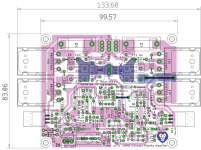
Eric, take a look at this version which has the high current traces copied to the top side also.

 Attached file removed. Please see later post for corrected version.
Attached file removed. Please see later post for corrected version.
Last edited by a moderator:
- Home
- Amplifiers
- Solid State
- 100W Ultimate Fidelity Amplifier