Very much agreed, hard to beat NE5534 for MMIn the case of a MM input, the best and least expensive show in town is the good old NE5534
Hi Drbilj,Hi StepResponse,
....... might be AD811.......
- Why 3 stages, amplification and RIAA can be comfortably fitted in 2
- Why R42-43 and C8-14? capacitors should be replaced with higher value resistors to loosely reference inputs to gdn, IMO. MC doesn't need capacitive load.
- If R9 and R6 are connected to each other and not ground (better use just one 500 Ohm) only much better CMMR will be achieved with no downsides
- Same probably applies for R11 and R19, but I am not familiar with special pin5 of ad844, so cant say for sure
- Also not sure what is the purpose of C2 C3 R7....
AD811 is an interesting (good?) op amp, but it does not have an OFFSET NULL function to "fight" with DC. The inverting input has a very low impedance - which is suitable for an ultra-low resistance MC cartridge.....
Why 3 stages? The first stage is the inevitable "love" that wants to watch an MC cartridge - an alternative to an ultra-quality step-up transformer. The second is the "necessary" evil subsonic filter. The third forms the low-frequency time constant for RIAA. If they can be reduced - offer!
Why R42-43 and C8-14? R 42/43 replace (imitate) a 3 ohm cartridge in the simulation. C8 C14 is a capacitance that wants to see almost any transistor as a Common Base.
The idea of R 9/6 is possible….
R 11/19 straighten (flatten) the upper end according to the Neumann curve.
C2/C3/R7 and with the corresponding ones in the other shoulder form a subsonic filter.
There may be a better way to tell you why the proposed circuit is a very bad idea and totally unsuited for the job.Yes - it is. But there is also an "original" and serious play on words - which is true!
What Carlos Candeias said there is in the logic of my words:
https://www.stereophile.com/content/bmc-phono-mcci-phono-preamplifier
Yes, the Cart is basically a voltage source but by connecting a Cart to a transimpedance amp that converts current into voltage, it will in series with 5R behave like a current generator with Iout = Vcart/5R.
In case of the proposed AD844 however, the current becomes Iout = Vcart/(5R+100R).
The generated current aka the audio signal is now attenuated by 5R/105R, thereby wasting a full 26dB.
That 26dB would be urgently needed to get the S/N near an acceptable level.
A S/N for a Cart+Amp should be at least 65dBA but preferably above 70dBA.
Hans
P.S. There is absolutely no special reason to look for a CFA amp when going for a transimpedance topology.
The minus input of low noise voltage amp with a feedback resistor from it’s output to set the gain, will have a very low impedance at it’s virtual input.
Hans
Last edited:

Everyone (engineer) has the right to an opinion and a position........a very bad idea and totally unsuited for the job....
But even such extremism (hatred) towards Carlos Candeias Current Injection inexplicable?
And his fans and my friends listen to unique Attack, Detail, Texture and Accuracy! If you can ever hear (simulate and measure LIVE) such a concept (topology) but with time aligned speakers -
you can "keep silent forever" - because before the facts and the gods are silent!
With respect
Trifonovaudio
Not sure why you are being so defensive. Hans has a massive reputation as a landmark audio designer.
In any event "Carlos Candeias Current Injection" is a discrete design with multiple parallel input devices (10 I think) in common base, and distributed RIAA. He does not use an inappropriate opamp that is guaranteed to be very noisy.
Have you actually built this phono stage?
In any event "Carlos Candeias Current Injection" is a discrete design with multiple parallel input devices (10 I think) in common base, and distributed RIAA. He does not use an inappropriate opamp that is guaranteed to be very noisy.
Have you actually built this phono stage?
G
The background noise of an LP is slightly below 60dBA.
That’s why a Cart+Amp should have a S/N of at least 65dBA.
So instead of fighting against simple facts, take some time to understand the basics, like the wasting of 26dB S/N as I explained in my previous email.
Hans
A S/N of 37dBA with a 0.3mV 5R Cart attached to your AD844 circuit proposal is not an opinion but a fact.Everyone (engineer) has the right to an opinion and a position....
But even such extremism (hatred) towards Carlos Candeias Current Injection inexplicable?
And his fans and my friends listen to unique Attack, Detail, Texture and Accuracy! If you can ever hear (simulate and measure LIVE) such a concept (topology) but with time aligned speakers -
you can "keep silent forever" - because before the facts and the gods are silent!
With respect
Trifonovaudio
The background noise of an LP is slightly below 60dBA.
That’s why a Cart+Amp should have a S/N of at least 65dBA.
So instead of fighting against simple facts, take some time to understand the basics, like the wasting of 26dB S/N as I explained in my previous email.
Hans
STEP RESPONSE. It seems you were humbly asking for a response and are now condemning those who offer anything negative. Seems you are bent on only confirmation bias of your existing beliefs.
I have built numerous phono stages including one using an input AD844 in single ended front end, ultimately feeding the output in being direct coupled from the cathode of a Winged "C" 6L6 (the finest 6L6 that I have ever laid my hands on). Although overall noisy the phono stage had an exceptional midrange and top end, ultimately finding it too "lossy" compared to others as best as I can describe it, as perhaps not dark enough in terms of blackness in the background.

From your diagram the overall input stage seems better than mine in that it uses lower value resistors from pin 5. Yet as Hans points out the noise seems worse in that the input resistance is doubled in using differential inputs. For example if you consider 0.3mV MC input imposed on the combined 100 Ohms input resistance this amounts to about 3uA input current. This current is mirrored into the combined 3.67 K Ohm connected to pin 5 = 11mV, being then filtered by the 2122 Hz pole by C1 and C6. Meaning that filtering is applied above 2122 for a signal being only 11mV at pin 5 to begin with.
This can account for the need to use a low noise device like the AD797. I don't see the need for such low values of R1/C1 though. Why not get the signal up out of the noise floor at pin 5 by using perhaps 4x resistors for R1 and R18 (with suitable values of C1 and C6 to obtain the 2122Hz pole).
In my experience the output buffer of the AD844 is not necessarily good to be using in conjunction with networks strung from the Tz node pin 5. I would be more inclined to run an NE5532 unity gain buffer off the AD844 pin 5 (if the gain was increased). By the way, capacitance directly connected to ground from pin 5 can cause output stage oscillations even if the output is not used unless a resistance of greater than about 47 Ohms is connected in series with pin 5. In the above network it uses 270 Ohms for R11 and R19, also causing the 2122 pole to shelve at about 25KHz.
Working in the noise floor can be pricey, notwithstanding the potential for sonic benefits in running fully differential. Digikey has AD844's at $20US each, AD797's at $25US each and the LT1028 about $18US, for a total of about $280US in stereo for the chips alone. The question is if something equally good or better can be done for far less. (By the way, I wouldn't mind paying this if it works... and you can purchase LT1115's for about half that price and very similar)
I have built numerous phono stages including one using an input AD844 in single ended front end, ultimately feeding the output in being direct coupled from the cathode of a Winged "C" 6L6 (the finest 6L6 that I have ever laid my hands on). Although overall noisy the phono stage had an exceptional midrange and top end, ultimately finding it too "lossy" compared to others as best as I can describe it, as perhaps not dark enough in terms of blackness in the background.
From your diagram the overall input stage seems better than mine in that it uses lower value resistors from pin 5. Yet as Hans points out the noise seems worse in that the input resistance is doubled in using differential inputs. For example if you consider 0.3mV MC input imposed on the combined 100 Ohms input resistance this amounts to about 3uA input current. This current is mirrored into the combined 3.67 K Ohm connected to pin 5 = 11mV, being then filtered by the 2122 Hz pole by C1 and C6. Meaning that filtering is applied above 2122 for a signal being only 11mV at pin 5 to begin with.
This can account for the need to use a low noise device like the AD797. I don't see the need for such low values of R1/C1 though. Why not get the signal up out of the noise floor at pin 5 by using perhaps 4x resistors for R1 and R18 (with suitable values of C1 and C6 to obtain the 2122Hz pole).
In my experience the output buffer of the AD844 is not necessarily good to be using in conjunction with networks strung from the Tz node pin 5. I would be more inclined to run an NE5532 unity gain buffer off the AD844 pin 5 (if the gain was increased). By the way, capacitance directly connected to ground from pin 5 can cause output stage oscillations even if the output is not used unless a resistance of greater than about 47 Ohms is connected in series with pin 5. In the above network it uses 270 Ohms for R11 and R19, also causing the 2122 pole to shelve at about 25KHz.
Working in the noise floor can be pricey, notwithstanding the potential for sonic benefits in running fully differential. Digikey has AD844's at $20US each, AD797's at $25US each and the LT1028 about $18US, for a total of about $280US in stereo for the chips alone. The question is if something equally good or better can be done for far less. (By the way, I wouldn't mind paying this if it works... and you can purchase LT1115's for about half that price and very similar)
Last edited:
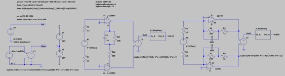
To bring the discussion back to a technical level, I made two preamp versions for a 0.3V 5R Cart.
One is the proposed version with the AD844 and the second one is based on a AD797
Only the first stage with the 75usec and the 3,18usec time constants were simulated , while the 3180usec and 318usec where put via Laplace in a Voltage dependent voltage source, also given the task to bringing the overall gain to 60dB@1Khz.
I have connected both AD844's T outputs to one network of dual values, which is the same as two individual networks but more elegant.
Cart B1 is connected to both AD844's minus inputs, who have a 50R internal impedance each.
The dual AD797's are configured as inverting amps, also having these 75usec/3.18usec corrections, where the Cart B2 is connected to their very low impedance virtual inputs.
Finally to be able to calculate the A weighted noise, a dedicated module was placed behind both amps.
1) the first image shows the circuit diagram with both amps.
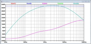
2) second image shows the Anti Riaa curve Vline in purple and both outputs Out1 and Out2, both having exactly the same perfectly flat 60dB gain.
Also the outputs of both A-Weighting modules are visible, confirming the intersection at 1Khz.
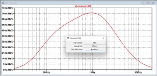
3) Third image shows the A_weighted noise referred to input from the AD844 version, being 4.05uV from 20Hz to 20Khz
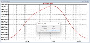
4) Last image shows the noise from the AD797 version, being 75.9nV over the same BW.
Now with a Cart producing 0.3mV@1Khz at 5cm/sec, S/N for the AD844 becomes 20*log(0.3mV/4.05uV) = 37.4dBA
The AD797 version on the other hand has a S/N of 20*log(0.3mV/75.9nV) = 71.9dBA.
Two reasons why the AD797 has a much better S/N: these amps have a 0,9nV/rtHz noise figure instead of the 2nV/rtHz, giving a 6.9dB advantage and the two 50R impedances in the AD844 give another 26.4dB disadvantage and there you are.
Hope this helps to make things clear.
Hans
One is the proposed version with the AD844 and the second one is based on a AD797
Only the first stage with the 75usec and the 3,18usec time constants were simulated , while the 3180usec and 318usec where put via Laplace in a Voltage dependent voltage source, also given the task to bringing the overall gain to 60dB@1Khz.
I have connected both AD844's T outputs to one network of dual values, which is the same as two individual networks but more elegant.
Cart B1 is connected to both AD844's minus inputs, who have a 50R internal impedance each.
The dual AD797's are configured as inverting amps, also having these 75usec/3.18usec corrections, where the Cart B2 is connected to their very low impedance virtual inputs.
Finally to be able to calculate the A weighted noise, a dedicated module was placed behind both amps.
1) the first image shows the circuit diagram with both amps.
2) second image shows the Anti Riaa curve Vline in purple and both outputs Out1 and Out2, both having exactly the same perfectly flat 60dB gain.
Also the outputs of both A-Weighting modules are visible, confirming the intersection at 1Khz.
3) Third image shows the A_weighted noise referred to input from the AD844 version, being 4.05uV from 20Hz to 20Khz
4) Last image shows the noise from the AD797 version, being 75.9nV over the same BW.
Now with a Cart producing 0.3mV@1Khz at 5cm/sec, S/N for the AD844 becomes 20*log(0.3mV/4.05uV) = 37.4dBA
The AD797 version on the other hand has a S/N of 20*log(0.3mV/75.9nV) = 71.9dBA.
Two reasons why the AD797 has a much better S/N: these amps have a 0,9nV/rtHz noise figure instead of the 2nV/rtHz, giving a 6.9dB advantage and the two 50R impedances in the AD844 give another 26.4dB disadvantage and there you are.
Hope this helps to make things clear.
Hans
Attachments
@ Hans, when I have seen this I had to take my PC out of my bag, not only that you are brilliant engineer, but also not lazy to draw when words are not sufficient
I'm also happy that my assumption is good:
Thanks!
I'm also happy that my assumption is good:
I have connected both AD844's T outputs to one network of dual values, which is the same as two individual networks but more elegant.
- If R9 and R6 are connected to each other and not ground (better use just one 500 Ohm) only much better CMMR will be achieved with no downsides
- Same probably applies for R11 and R19, but I am not familiar with special pin5 of ad844, so cant say for sure
Thanks!
What I find also interesting is simulation of AD797 with -71.9db noise.The AD797 version on the other hand has a S/N of 20*log(0.3mV/75.9nV) = 71.9dBA.
In these posts:
https://www.diyaudio.com/community/...ono-preamplifier-thoughts.414816/post-7746541
https://www.diyaudio.com/community/...ono-preamplifier-thoughts.414816/post-7745780
I measured, not simulated, SSM2017 at -77,3 and -75,9 db for trans-impedance and voltage mode respectively.
SSM2017 and AD797 have pretty much same spec on voltage noise.....
Sorry, forgot to mention, I used simulated cart load 33 Ohm, Hans simulated with 5 Ohm, that just emphasize difference more. My gain was also "only" 40db.
Input devices can be 2, 10 or 40......?....In any event "Carlos Candeias Current Injection" is a discrete design with multiple parallel input devices (10 I think) in common base, and distributed RIAA.
Have you actually built this phono stage?....
It is the idea or the principle that matters!
We listened and compared my version and BMC MCCI.
The sound is very close with a similar flavor. We couldn't we find a "problem" due to the lack of
an audiophile PSU at Carlo Candeias's RIAA. But because of the low order subsonic filter there
was a bit of bouncing on the bass diaphragms...
We couldn't measure or hear any lower noise with it - probably because of the high gain.
Speaking of another(proper) op amp.....
Who else can work without negative global feedback??
We listened and measured..........like the wasting of 26dB S/N....
That "26dB S/N" does not audibly dominate the overall balance scheme!
Probably also due to the high frequency time constant at the TZ point.
Dear Hierfi,
Oh, I'm always critical - especially of myself! But when something is "spitted" and denied
(BMC MCCI) - the better should be published immediately (together)! ...... There was no such post!!
Your technical comment is correct, possible and well reasoned - for which thank you!
Oh, I'm always critical - especially of myself! But when something is "spitted" and denied
(BMC MCCI) - the better should be published immediately (together)! ...... There was no such post!!
Your technical comment is correct, possible and well reasoned - for which thank you!
After the initial "excess" - now the general tone is more normal and the technical rationale understandable.😉To bring the discussion back to a technical level,....
Looking at the input network as outlined by STEP RESPONSE it isn't clear that this is the best approach to achieve a balanced output using a pair of AD844's. An alternative approach would configure the network as per below:To bring the discussion back to a technical level, I made two preamp versions for a 0.3V 5R Cart.
One is the proposed version with the AD844 and the second one is based on a AD797
Only the first stage with the 75usec and the 3,18usec time constants were simulated , while the 3180usec and 318usec where put via Laplace in a Voltage dependent voltage source, also given the task to bringing the overall gain to 60dB@1Khz.
I have connected both AD844's T outputs to one network of dual values, which is the same as two individual networks but more elegant.
Cart B1 is connected to both AD844's minus inputs, who have a 50R internal impedance each.
The dual AD797's are configured as inverting amps, also having these 75usec/3.18usec corrections, where the Cart B2 is connected to their very low impedance virtual inputs.
Finally to be able to calculate the A weighted noise, a dedicated module was placed behind both amps.
1) the first image shows the circuit diagram with both amps.
2) second image shows the Anti Riaa curve Vline in purple and both outputs Out1 and Out2, both having exactly the same perfectly flat 60dB gain.
Also the outputs of both A-Weighting modules are visible, confirming the intersection at 1Khz.
3) Third image shows the A_weighted noise referred to input from the AD844 version, being 4.05uV from 20Hz to 20Khz
4) Last image shows the noise from the AD797 version, being 75.9nV over the same BW.
Now with a Cart producing 0.3mV@1Khz at 5cm/sec, S/N for the AD844 becomes 20*log(0.3mV/4.05uV) = 37.4dBA
The AD797 version on the other hand has a S/N of 20*log(0.3mV/75.9nV) = 71.9dBA.
Two reasons why the AD797 has a much better S/N: these amps have a 0,9nV/rtHz noise figure instead of the 2nV/rtHz, giving a 6.9dB advantage and the two 50R impedances in the AD844 give another 26.4dB disadvantage and there you are.
Hope this helps to make things clear.
Hans

The moving coil cartridge is a floating source. As far as the upper AD844 is concerned the voltage developed across the inputs is a function of the input current imposed on ~50 Ohm input impedance as specific to the +ve terminal of the AD844. This potential also appears across the lower AD844, however this generates equal opposing currents through the ~50 Ohm into the terminal connected to ground. It seems likely this parallel connection would generate considerably less noise (and you can always start stacking too...).
Last edited:
Not only does it seem likely, but it almost certainly is!....It seems likely this parallel connection would generate considerably less noise....
Dear Drbulj,Dears,
So i start again (this time with correct bandwidth 😎 ), SSM2017 in current mode (bus summing) , Rg 33 Ohm, Rin 2 x 47k.
Input from soundcard is 1V reduced by 47k and 33 for approx 2850 times to bring it on MC cart level
Output from Amp : 314 mV, gain approx x100 or 40db
View attachment 1337864
SNR is now -77,3 db, THD 0.0012%. Now it looks right.
In my opinion above will be masked by even the best cartridge - TT - LP combo and make it irrelevant... Such circuit can go in as it is, SSM2017 is great...
But I'll continue.
PS, for some reason also 50 Hz noise vanished today????
Maybe you can help me in understanding the above image with due respect for all your extensive efforts so far.
To summarize when I'm correct:
A Cart, operating in current mode, is represented by Rg=33R giving a gain of 10K/33R = 303 or 49,6dB.
Signal on Cart is from a 1Volt@1Khz source, fed through two 47K resistors on Rg, causing 0.35mV on Rg.
With the calculated gain of 303 this should result in106mV, which corresponds nicely to within 0.77dB with the -20.26dBFS as shown in the image .
But the spectral 1Khz line in your Image is at -11.19dBV, or at 276mV, which is 2.8 times or 9.07dB higher as the -20.26dB, but nevertheless the -11.19dB was used to calculate the S/N.
There must be something I'm missing here in the calculation.
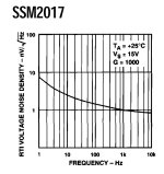
The other thing I don't understand is the shape of the noise spectrum in the image which increases by almost 30dB from 20Hz to 20Khz, while the SSM2017's spectrum as shown in the attachment goes down with increasing frequency ?
Sorry for all my questions, but be also aware that Riaa and A-weighting both improve the S/N by almost 10dB, so without one should measure somewhere in the lower 60dB range.
This can be confirmed by a quick check.
The SSM2017 produces ca. 1.5nV/rtHz at a gain of 303.
For a BW from 20Hz to 20Kz this results in sqrt(20Khz)*1.5nV/rtHz = 212nV.
For a cart producing 0.35mV, S/N now becomes 20*log(0.35mV/212nV) = 64.4dB without Riaa and without A-weighting.
With Riaa this becomes ca. 70.4dB and with added A-weighting ca. 74.4dBA.
Hans
Attachments
Who exactly was reacting in a very defensive way, when you call that initial "excess" I can agree.After the initial "excess" - now the general tone is more normal and the technical rationale understandable.😉
We listened and measured......
That "26dB S/N" does not audibly dominate the overall balance scheme!
Probably also due to the high frequency time constant at the TZ point.
When you measured, what did you measure, what was the setup and with what Cart.
With no further details this tells nothing.
26dB signal attenuation from a 5R Cart has nothing to do with overall balance but everything with worsening the S/N by 26dB.
The conclusion can only be that you still do not get the facts.
So, for me this chapter will be closed.
Hans
I've been doing some simulation runs on Richard Lee's "Duraglit" MC stage - basically a battery powered complementary common base stage. This is flat, with sufficient gain to feed around 5mV into a MM RIAA stage.
I've been using models in Microcap 12 for the ZTX851/951. Collector current and load resistor are set to optimise noise and set the gain. Two resistor values.
First using a 5 ohm cartridge with 0.3mV output. Input noise density 353pV/root Hz. The noise from the 5 ohm cartridge resistance is 288pV/rootHz
Going to the opposite resistance end, the DL103 with 40 ohm resistance. Input noise density 1.05nV/rootHz. The noise from 40ohms is 0.814nV/rootHz.
With shorted input, with resistor values set for the 5 ohm first example suggests the input noise is around 200pV/rootHz That is exceptionally quiet, and supports Richard' assertion that "it is probably the lowest noise such device in the known universe"
I'm tempted to agree with him.
There is nothing to stop this little stage operating in balanced mode. I'm just going to try that.
- Home
- Source & Line
- Analogue Source
- Fully balanced MC phono preamplifier thoughts