OK I did some reading, and thinking when I should have been sleeping. 2nd order distortion is harmonic distortion it is at integer multiples (good for guitar overdrive), both drivers should make very similar levels of 2nd order harmonics. 3rd order is non-linear and composed of frequencies that are not harmonic and added or subtracted from the fundamental frequency (good for guitar fuzz). So if 2nd order largely disappears, then 3rd order can be the loudest distortion component. Also, 3rd order distortion from the inside woofer will pass through the outside woofer adding to its 3rd order distortion and thereby increase the total 3rd order distortion. This is more distortion than a single driver speaker but wouldn’t it be the same as any two woofer system? I’m thinking not, or line sources would have tremendous levels of 3rd order distortion. What am I missing?
IMHO @Arthur Jackson , what you are possibly missing is that - in my design, I mean - the two speakers do not operate in a Push-Pull, but in a Parallel Tandem. Push-Pull would be magnet to magnet or cone to cone disposition, with reversed polarities. Here, the speakers are cone to magnet installed, and in polarity.
A Push-Pull will cancel distortion - two speakers working instead of one - but the maximum cancellation occurs for 2nd order and even harmonics, due to the symetry. The 3rd order and uneven harmonics are not better cancelled than in the Parallel Tandem.
A Parallel Tandem will cancel distortion - again, two speakers working instead of one - but the cancellation for the 2nd Order and even harmonics is reduced due to the abscence of symetry. Therefore, there will be more distortion here, but the balance between 2nd and 3rd orders will be probably better.
I would compare this to a 2 tubes Push Pull output stage vs. a Single Ended parallel output stage, both operating in the same class A conditions.
T
Well, it’s Daves argument. I’m just trying to understand it. Personally, I think distortion goes down in multiple woofer systems. In isobaric it’s different because only one of the drivers is playing into the room so, to get the same loudness you will get more distortion than two woofers playing into a room, but less distortion than one non-isobaric woofer playing into a room. -? That’s kind of a question, I have no data to back up my thoughts.third order distortion can come down, too?
If the drivers are mounted linkwitz alike compensating nonlinearities of the suspensions.
Did anyone measure that this arrangement only helps second order distortion behaviour?
Or is this statement derived only from theory?
It would be very interesting to see some distortion measurements.
I found some data! Isobaric seems to reduce 2nd and 3rd order distortion in the lowest frequencies, at least in this one test.
https://www.diyaudio.com/community/threads/some-driver-distortion-measurements.400273/
https://www.diyaudio.com/community/threads/some-driver-distortion-measurements.400273/

Thank you @Arthur Jackson for posting that link to @Patrick Bateman 's study ! 😎😎😎
https://www.diyaudio.com/community/threads/some-driver-distortion-measurements.400273/post-7377393
It corroborates what I have found (and wrote in post #161 above) on the Isobaric subject, and matches what I am experimenting here in my project (Cone to Magnet arrangement).
At least, it is interesting and reassuring ! 🙂
T
Regarding distortion, with Isobaric system. It is not the same as using 2 drivers in a conventional system with one mounted reversed. Assuming identical distortion from both drivers, in that case one driver has even order distortion with inverted phase and for the summed SPL from both the even order distortion cancels. (That's not entirely true due to the nonlinearity of the air compliance for a sealed box). But with an isobaric system only the front driver is radiating and the effect of the distortion does not cancel in the radiated SPL. You have to look at the driver motion. What happens is that the forces in the isobaric change include the nonlinear effect from the driver motion and they don't necessarily cancel. Please read my web page on this here to get a better understanding. http://musicanddesign.speakerdesign.net/Isobaric.html I only consider nonlinearity in the driver suspension and box air compliance. Othe rnonlinearities can arise int eh motor and damping.
In summary (if you don't want to read all the details) the figure to the left is from a isobaric with push-pull mounting. To the right is the same system but not in push-pull format. The left figure shows some reduction of 2nd order (blue symbols for front driver) but higher 4th order and 6th order.


In summary (if you don't want to read all the details) the figure to the left is from a isobaric with push-pull mounting. To the right is the same system but not in push-pull format. The left figure shows some reduction of 2nd order (blue symbols for front driver) but higher 4th order and 6th order.
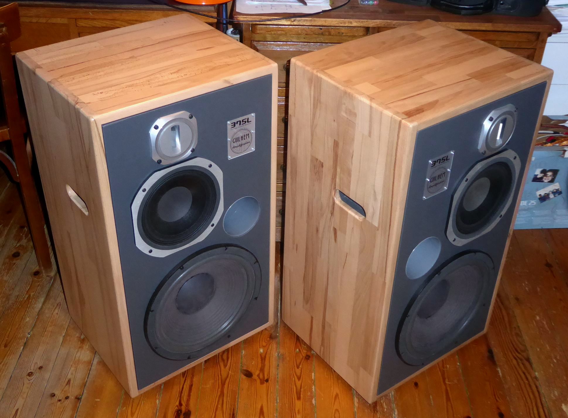
At the favour of a bit cooler day, work could progress...
Radiusing the edges, sanding, addition of the recessed lateral handles and the bases (for optional installation on Klipsch Heresy I slanted risers) :

Details of the lateral handles :

Wait and See ! 😉
T
Radiusing the edges, sanding, addition of the recessed lateral handles and the bases (for optional installation on Klipsch Heresy I slanted risers) :
Details of the lateral handles :
Wait and See ! 😉
T
I like the idea of built in handles. I moved a lot in the service and movers always broke my speakers, Probably because they were heavy.
I like the idea of built in handles. I moved a lot in the service and movers always broke my speakers, Probably because they were heavy.
Absolutely ! Well, it is no coincidence that the PA loudspeakers have handles, right ? That said, it is barely present on Hi-Fi speakers, certainly because it would not be nice or presentable in terms of aesthetics, and moving them is also rare... Although...
I think that I found an acceptable compromise for the look here - I first experimented this on my 375L : built-in handles simili-covered inside, placed at gravity centre vertical line...
OK, it's an additional work to achieve, but really, I never would have imagined how safer and easier carrying is for such large speakers with those handles ! That's why I repeated the tip on my 475L.
T
Will there be additional internal bracing?At the favour of a bit cooler day, work could progress...
Radiusing the edges, sanding, addition of the recessed lateral handles and the bases (for optional installation on Klipsch Heresy I slanted risers) :
View attachment 1341866
Details of the lateral handles :
View attachment 1341867
Wait and See ! 😉
T
...... placed at gravity center vertical line...
T
Good thinking and nice work.
Will there be additional internal bracing?
Yes. There will be some additional bracing - to be studied : I prefer present all the internal equipment in the cabinet, and then devise a suitable panel bracing and panel vibration damping.
T
Good thinking and nice work.
Thanks @john k... ! 🙂
For the moment, temperature is to hot to work outside, so I am preparing a temporary-test crossover :
T
Filter response estimation with drivers flat SPL responses and flat 8 ohm impedance on tweeter axis.

Thank you @kaameelis for the simulation of my crossover structure ! 😎
I suppose that you take the dimensions on my template in my post #114 :
https://www.diyaudio.com/community/...xperiences-any-advantages.414066/post-7742865
For my curiosity : is your simulator able to work from the LC values ? 🤔
If yes, then would you mind simulate with the set of approximating values below - direct from my drawer ? It's what I plan for a first test... 😉

The calculated FC are :
L1-C1 = 306Hz
L2-C2 = 2340Hz
L3-C3 = 8761Hz
Thanks in advance ! 🙂
T
I suppose that you take the dimensions on my template in my post #114 :
https://www.diyaudio.com/community/...xperiences-any-advantages.414066/post-7742865
For my curiosity : is your simulator able to work from the LC values ? 🤔
If yes, then would you mind simulate with the set of approximating values below - direct from my drawer ? It's what I plan for a first test... 😉
The calculated FC are :
L1-C1 = 306Hz
L2-C2 = 2340Hz
L3-C3 = 8761Hz
Thanks in advance ! 🙂
T
You should build these caculated crossovers and measure them, so we all can see how far you get with such "universal constant resistance formula".
Vituixcad can account in simulation nearly all parameters needed, speaker drivers positions, case shape, filter elements impedance, SPL responses and also it have automatic filter elements tuning function to target. In my simulation drivers positions are taken from your drawing, L and C values in simulation are turned visually by filter chart, it is easy to turn to what ever value needed. Y 0 is at tweeter center. Only thing I did not know how to simulate is isobaric alignment of bass drivers.
I suggest to download Vituixcad, find/measure drivers responses and impedance data and make your own simulation, this can avoid later problems as my simulations before with 3 way and real driver data have shown, drivers real impedance have big influence on resulting SPL and standard formula calculated filter not give best result.
I suggest to download Vituixcad, find/measure drivers responses and impedance data and make your own simulation, this can avoid later problems as my simulations before with 3 way and real driver data have shown, drivers real impedance have big influence on resulting SPL and standard formula calculated filter not give best result.
Vituixcad can account in simulation nearly all parameters needed, speaker drivers positions, case shape, filter elements impedance, SPL responses and also it have automatic filter elements tuning function to target.
Yes... This is a software that I'll have to set up... Added to my list ! 😉
The temporary crossovers are built for listening tests :
T
Last filter element values give this result with drivers flat response and flat 8 ohm impedance.


Thanks again @kaameelis !
Yes, my new set of values is probably not premium - I have the intuition that shifting to 1.8µF instead of 2.2µF for the TW-HM and 6.8µF insted of 4.7µF for the HM-LM will certainly compensate the depression centered on 2kHz, which occurs because FC2 is 2815Hz instead of 2340Hz, and FC3 is 8761Hz instead of 9600Hz.
I note it, and will listening test it !
T
- Home
- Loudspeakers
- Multi-Way
- ISOBARIC sealed enclosure... Any experiences? Any advantages?