Last edited:
We'll see @kaamelis : I did not had the time to work on the project today... I expect to experiment tomorrow !
La carte n'est pas le terrain, as we say in France... Over the years to I learnt to be wary of acoustic measurements and simulations. That said, in no way I deny acoustic measurements nor simulations, indeed ! And I very appreciate your insight : this is another way to approach the problem that I do not have on hands for the moment - so thanks again !😉
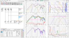
Here are the resistors values that I plan to test tomorrow :
TW : RS=2R2, RP=15R / att=-3.27dB / AVG Z on the frequency band (8K-15K)=7R
HM : RS=1R5, RP=27R / att=-2.07dB / AVG Z on the frequency band (3K-8K) = 7R
LM : RS=3R3, RP=22R / att=-3.31dB / AVG Z on the frequency band (300-3K) = 10R5
T
Listening tests update :
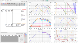
The 612SP-4W crossover begins to work fine with these values below :

The listening position : seated in a sofa, head at 3m from the speakers, 2.50m between speakers axis, speakers off axis 15° horizontal, vertical tilt back 8°.

T
The 612SP-4W crossover begins to work fine with these values below :
The listening position : seated in a sofa, head at 3m from the speakers, 2.50m between speakers axis, speakers off axis 15° horizontal, vertical tilt back 8°.
T
Even that is only a crossover less worse than the previous. Maybe you should explain that only with measurements inside the actual cabinet the simulation will be close to reality. Not measuring while building speakers is like driving a night, lights off and eyes closed. The only possible result will be an accident.Better version.
It have huge sensitivity because driver ranges overlapping, but also very low summarized impedance because of overlapping and high Q of filters.
... And if you move your measuring microphone by less than 10cm, all your simulations - with or without "exact" datas - are ruined.
I don't even speak about the influence of the room, which has nothing to do with the usual anechoic one meter test.
I choose the opposite way - partly because I do not have the measuring gear on hand anymore for the moment : I built the speaker and set it up as best by listening and comparing, and then I'll make measurements in the conditions I set it up. Doing this, you discover surprises, good or bad...
It is never considered well not to do like everyone else... Maybe I'm driving a night, lights off and eyes closed, but I am not deaf...
T
tubelectron
Is it worth sharing what you done, nobody is interested and only invokes arguments. Obviously, if it can't be simulated it does not exist. In my opinion everything that was designed before simulators could not exist.What if the measurements are perfect but it sounds crap. Also what if it sounds great but the measurements are disagreeable with anyone else. Who did you make these speakers for? You? I guess so. Enjoy what you have crafted, that is the essence. No perfect loudspeaker was ever built for any room.
tubellecron, if you do not have the measurement equipment, you are banned from building anything at all. If it is not simulated and then accurately verified by measurement, it is not worth listening too. You have to follow the true design path, there is no other way! 🤣 🤣 🤣
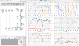
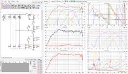
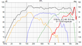
I wanted to learn a bit about series crossover so I traced the FR/ZR and calculated the curves in cabinet according to the volume indicated above. I played a bit with your project in VCad: All driver FR and ZR are simulated in cabinet with the diffraction tool. So here it is: FR has a -0.25 dB/oct. slope but impedance is very low, about 2 Ohm, so you should consider a passive biamp.
Let me know if you want the files of the project.


Let me know if you want the files of the project.
Microphone location is one parameter in simulation, it can be changed for simulation.... And if you move your measuring microphone by less than 10cm, all your simulations - with or without "exact" datas - are ruined.
I don't even speak about the influence of the room, which has nothing to do with the usual anechoic one meter test.
My simulation surely is not 100% correct as for datasheets measurements are done on test panels and polar plot data is not used in simulation.
Only thing I am sure and get this from simulation, is that polarity of LM and TW must be changed.
Other issue I am not so sure is that T2030 is not suitable if used in range higher than 8700 Hz, it have there bad SPL line.
I attached also Vituixcad simulation file with used data files as zip.
Attachments
Last edited:
OK - Thank you Guys - I'll keep the rest of the story for me, given that it is of no interest, just because you can't play with your simulators...
Who are you to give me lessons ? Poor man... 🙁
Over.
T
Is it worth sharing what you done, nobody is interested and only invokes arguments. Obviously, if it can't be simulated it does not exist. In my opinion everything that was designed before simulators could not exist.
Who are you to give me lessons ? Poor man... 🙁
Over.

T
Last edited:
This was not a dig at you tubelectron, this is just general, when someone wants to share his "success" then he get shouted down. I just cant get it how low your listening area roof is. 😱 you cannot jump up with joy?
I have built some isobarik subwoofers in the past, both sealed and ported.
What people often forget is that the isobarik chamber contains air, and that air has some weight. Each liter air in the isobarik chamber weights 1,29 grams . There may be 10 liters inside the isobarik chamber, so 13 gram extra ( depending of which type of isobarik coupling there is ) . This air weight, together with the dual weight of the cones in an isobarik configuration lowers the loudspeakerdrivers combined resonans frequency in the box, i.e. the fb will be slightly lower.
So, when a single driver in an optimal box has a fb of maybe 40 Hz, the same driver in an isobarik configuration plus the air weight inside the chamber will lower the systems fb to maybe 35 Hz .
Long time ago, this was an easy way to use cheaper drivers making them behave like real subwoofer drivers. Nowadays there are more subwoofer options with heavy cones and big motor systems, making the isobarik approach slightly less appealing.
With isobarik, the backpressure that dominates the front driver is coming from the inner driver - not the cabinet in the same degree.
This will make the bass better articulated compared to a single driver .
Here is Ivor Tiefenbruns ( Linn products ) isobarik patent :
https://patentimages.storage.googleapis.com/cb/2c/6a/a88bb919642efb/US4008374.pdf
The Linn keltik, famous for outstanding deep articulated bass.
Last edited:
Maybe I will try Isobarik one time as I get only cheapo drivers in egypt.
Now I make a subwoofer with two 25cm drivers, one turned
 around (and turned phase), impulse compensated working together in reflex box of 170 liters. For home cinema corner placed.


for cone stability they got one sided aluminium foil
Now I make a subwoofer with two 25cm drivers, one turned
for cone stability they got one sided aluminium foil
@Audientid14 : thanks for your insight and the link to the Isobarik patent... I searched for some in that field, but often found incomplete descriptions or samples.
I read this :


The description above and the matching figures - from the patent - states that "an absorbent curtain and/or a filling is provided in the Isobaric chamber" to reduce "inter-speaker distortion", if I can say so.
Surprisingly, Vance Dickason recommends - in its well-known book The Loudspeaker's CookBook - that "no fill material sould be installed in the Isobaric chamber, if not felt sheets that could be fixed on the inside faces".
Here's what I did - empirically :

I covered the internal faces of the chamber with 40mm Cotton Wool, in order to prevent any internal resonances...
So what did you do about the chamber : absorbent ? No absorbent ? Which kind, if yes ?
T
I read this :
The description above and the matching figures - from the patent - states that "an absorbent curtain and/or a filling is provided in the Isobaric chamber" to reduce "inter-speaker distortion", if I can say so.
Surprisingly, Vance Dickason recommends - in its well-known book The Loudspeaker's CookBook - that "no fill material sould be installed in the Isobaric chamber, if not felt sheets that could be fixed on the inside faces".
Here's what I did - empirically :
I covered the internal faces of the chamber with 40mm Cotton Wool, in order to prevent any internal resonances...
I have built some isobarik subwoofers in the past, both sealed and ported.
So what did you do about the chamber : absorbent ? No absorbent ? Which kind, if yes ?
T
- Home
- Loudspeakers
- Multi-Way
- ISOBARIC sealed enclosure... Any experiences? Any advantages?
