Not if I can avoid it.Would you like to try gluing foil and etching the desired design?
Etching is messy and will always etch some of the traces too so I would have to be careful and time how long they are dipped. While I love to complain about the cutter, when it does work it works really well. The consistency is amazing.
But I got thinking some more about how the yield for the long membrane will be awful and how it rips all the time because of the scalpel type blade: isn't that exactly what the rotary blade is meant to solve?
Instead of a dragging cut it has a rolling cut which should make ripping a non issue. Even better is that as far as I can read it fits in the right tool holder so if we absolutely need tight curves we could, in theory, make those cuts with the normal scalpel type blade. Although those might be cuttable with the rotary tool too as long as we adjust some margins.
EDIT:
Here is a sketch where the blue uses a rotary cut.
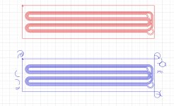
Seems to only need to do the swirl around the outer edges which is great since I could just have more margin around. And if not then with the segmented setup I can always mark the edges to be cut with the normal blade. Although in any case it is probably a good idea to adjust the drawing and reduce the amount of sharp corners in the actual membrane.
Last edited:
I've ordered a rotary blade to try it out, if I am lucky it will arrive before the weekend.
Another possible solution is to add a sticky stabilization layer on top of the foil before cutting. The idea is that this extra layer will be more stiff and prevent rips. Kind of how Silhouette sells iron on fabric stiffener to help cut fabrics where the glue is dissolvable in water. I just happen to have some vinyl transfer paper lying around so I will definently try that.
Until now I've used the transfer paper when I cut aluminum with pre applied adhesive, to transfer to the mylar. But it will be worth trying to first add a vinyl transfer sheet on the foil before cutting. I can always use another transfer sheet to transfer the now foil + transfer paper 🙂
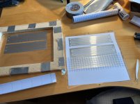
Here are some membranes I cut last weekend before I realized they were all too big since Silhouette Studio rescaled my .dxf drawings...

Last edited:
More progress!
I took apart the massively distorting push-pull driver from post https://www.diyaudio.com/community/...o-be-used-in-a-dipole-cbt.412132/post-7749361 and the suspension on one side is definently not great:
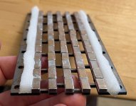
The other side looks better but after closer inspection it too wasn't as flat as I want it to be. It curves inwards a lot on one side:


The glue on the weatherstrip is causing a lot of problems because it is so hard to get it applied perfectly uniform. It sticks to the magnets or itself and bunches up. I think it would be best to use foam without glue. I could use the weatherstrip but not peel of the glue backing film but that might rattle so might be a better idea to cut one of my sheet foams. And if I want glue then I should add glue myself. Say contact adhesive so I can ensure the foam only sticks to the steel plates and not the plastic edge or the magnets.
Apart from that I have updated my gluing jig, now my rows look a lot better!
Left is old, right is new.
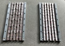
While definently ugly I don't believe the ugly magnets will impact performance enough for my tests so I will leave it as it is for now, they are only tests after all. But if I need to I could rip away the worst offending magnets and re glue them with the new jig.
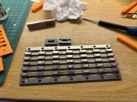
Both first glue every odd magnet in the rows, that is the same for both. But the jig to glue the even magnets differs. Here is a pic of the new jig. I place the small grey plastic pieces in between two magnets and then add push a magnet through the slot with some glue applied. The jig in the image is v1 though, I made a v2 which had a fillet on the top to make it easier to push down the magnet I want to glue.
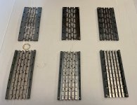
And lastly I have my 6 plates I want to test with this weekend:
Leftmost is the physically curved plate, middle is the standard version and the rightmost is the PDR variant where the suspension area will be open and maybe add more output without just being bad? The plastinc thingys is to ensure that the suspension has support in between the holes. It was cheaper to make it in plastic than to laser cut the holes 🙂.
The plan for tomorrow is to make a lot of membranes. I want membranes for the above test planars, and then start measuring. I might get some measuring done by tomorrow but if not then I'll get the rest done by Monday.
On top of comparing the above I plan to test:
I took apart the massively distorting push-pull driver from post https://www.diyaudio.com/community/...o-be-used-in-a-dipole-cbt.412132/post-7749361 and the suspension on one side is definently not great:

The other side looks better but after closer inspection it too wasn't as flat as I want it to be. It curves inwards a lot on one side:


The glue on the weatherstrip is causing a lot of problems because it is so hard to get it applied perfectly uniform. It sticks to the magnets or itself and bunches up. I think it would be best to use foam without glue. I could use the weatherstrip but not peel of the glue backing film but that might rattle so might be a better idea to cut one of my sheet foams. And if I want glue then I should add glue myself. Say contact adhesive so I can ensure the foam only sticks to the steel plates and not the plastic edge or the magnets.
Apart from that I have updated my gluing jig, now my rows look a lot better!
Left is old, right is new.

While definently ugly I don't believe the ugly magnets will impact performance enough for my tests so I will leave it as it is for now, they are only tests after all. But if I need to I could rip away the worst offending magnets and re glue them with the new jig.
Both first glue every odd magnet in the rows, that is the same for both. But the jig to glue the even magnets differs. Here is a pic of the new jig. I place the small grey plastic pieces in between two magnets and then add push a magnet through the slot with some glue applied. The jig in the image is v1 though, I made a v2 which had a fillet on the top to make it easier to push down the magnet I want to glue.

And lastly I have my 6 plates I want to test with this weekend:
Leftmost is the physically curved plate, middle is the standard version and the rightmost is the PDR variant where the suspension area will be open and maybe add more output without just being bad? The plastinc thingys is to ensure that the suspension has support in between the holes. It was cheaper to make it in plastic than to laser cut the holes 🙂.

The plan for tomorrow is to make a lot of membranes. I want membranes for the above test planars, and then start measuring. I might get some measuring done by tomorrow but if not then I'll get the rest done by Monday.
On top of comparing the above I plan to test:
- with vs without a filled plane around the traces
- kapton vs mylar
- 3 mm vs 4 mm mechanical xmax
Last edited:
Great success!
I tested to add the vinyl transfer sheet on top of the foil before cutting and it turned out great! It solved ripping, in total I cut 15 membranes and didn't have a single rip! All membranes were cut perfectly!
It cut so well that I skipped segmenting the membrane and cut it all in one go. I also reduced the gap from 1 mm to 0.75 mm. I think I can go down to 0.5 mm no problem with this method.
The only problems I had was that at first I didn't cut deep enough so the knife didn't always cut through the aluminum foil. But I increased the cut depth by 20 um and made it cut in 2 passes and then all those problems went away. I cut 9 membranes in a row that all cut and weeded perfectly without any issues.
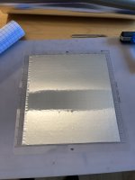
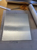
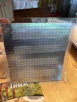
Something worth noting though is that weeding is more laboursome since now we need to weed away the transfer sheet from the foil. The hardest part is the outside fill since it is wide but the traces are pretty easy. The only risky part is to peel up a corner of the sheet somewhere. But with my 30 um foil it was easy enough to do with a tweezer. In total I weeded 9 membranes and didn't ruin a single membrane. So while it is more laboursome that wouldn't be a problem even on a full length 2 m membrane.
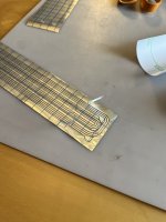
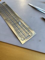
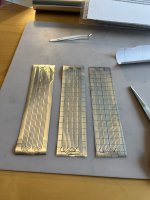
Though if you use much thinner foil and need to be more careful then I think it would work to add a small bit of tape that is more sticky than the transfer sheet and then pull the tape. Or glue a thin wire or similar with a small amount of superglue and then pull the wire. Then you won't have to push against the edges of the foil with a tweezer and risk damaging it.
But all in all I made 9 membranes
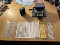
After corrugation:
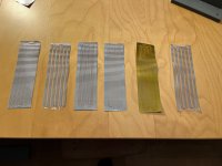
EDIT: If you wonder why there are only 6 membranes after corrugation but 9 membranes before... I wanted to try the standarb membrane but with smaller corrugating wheels to get 0.8 mm peak-to-peak corrugations instead of 1.0 mm peak-to-peak which I have used until now. But something didn't work so the membranes were just ruined so I postponed experimenting with that to the future.
Finally I have 6 membranes I will aim to test tomorrow:
My plan is to assemble the curved planar with a standard membrane and then not touch it. But to swap around the others and keep the curved as a reference.
In theory the membranes without filled planes should be more efficient but the question is if they will still hold the corrugation enough. I do have quite thick aluminum at 30 um so it might be enough.
I tested to add the vinyl transfer sheet on top of the foil before cutting and it turned out great! It solved ripping, in total I cut 15 membranes and didn't have a single rip! All membranes were cut perfectly!
It cut so well that I skipped segmenting the membrane and cut it all in one go. I also reduced the gap from 1 mm to 0.75 mm. I think I can go down to 0.5 mm no problem with this method.
The only problems I had was that at first I didn't cut deep enough so the knife didn't always cut through the aluminum foil. But I increased the cut depth by 20 um and made it cut in 2 passes and then all those problems went away. I cut 9 membranes in a row that all cut and weeded perfectly without any issues.


Something worth noting though is that weeding is more laboursome since now we need to weed away the transfer sheet from the foil. The hardest part is the outside fill since it is wide but the traces are pretty easy. The only risky part is to peel up a corner of the sheet somewhere. But with my 30 um foil it was easy enough to do with a tweezer. In total I weeded 9 membranes and didn't ruin a single membrane. So while it is more laboursome that wouldn't be a problem even on a full length 2 m membrane.


Though if you use much thinner foil and need to be more careful then I think it would work to add a small bit of tape that is more sticky than the transfer sheet and then pull the tape. Or glue a thin wire or similar with a small amount of superglue and then pull the wire. Then you won't have to push against the edges of the foil with a tweezer and risk damaging it.
But all in all I made 9 membranes

After corrugation:

EDIT: If you wonder why there are only 6 membranes after corrugation but 9 membranes before... I wanted to try the standarb membrane but with smaller corrugating wheels to get 0.8 mm peak-to-peak corrugations instead of 1.0 mm peak-to-peak which I have used until now. But something didn't work so the membranes were just ruined so I postponed experimenting with that to the future.
Finally I have 6 membranes I will aim to test tomorrow:
- For the standard planar
- 1x 4 rows, filled plane (one for the flat version and one for the curved)
- 1x 4 rows, filled plane but in kapton
- 1x 4 rows, no filled plane except at suspension
- For the curved planar
- 1x 4 rows, filled plane
- For the PDR planar with open holes at the suspension
- 1x 6 rows, filled plane
- 1x 6 rows, no filled plane
My plan is to assemble the curved planar with a standard membrane and then not touch it. But to swap around the others and keep the curved as a reference.
In theory the membranes without filled planes should be more efficient but the question is if they will still hold the corrugation enough. I do have quite thick aluminum at 30 um so it might be enough.
Last edited:
I also measured the resistance of all membranes after soldering some wires (all wires same length):
4 trace rows with fillled plane:
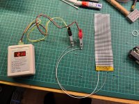
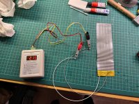
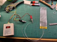
4 trace rows with suspension row:
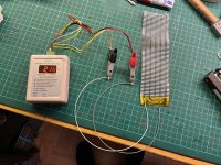
6 trace rows:
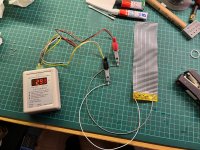
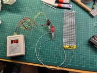
There is some variance but not that much. The 4 trace row membranes have the following resistance in ohm:
2.21
2.15
2.16
2.16
And that is after I solder some wires, it could be that the membrane with slightly higher resistance is because of my solder job. But even if not then the consistency seems pretty great.
4 trace rows with fillled plane:


4 trace rows with suspension row:

6 trace rows:


There is some variance but not that much. The 4 trace row membranes have the following resistance in ohm:
2.21
2.15
2.16
2.16
And that is after I solder some wires, it could be that the membrane with slightly higher resistance is because of my solder job. But even if not then the consistency seems pretty great.
Great news, OllBoll! And impressive results!
Can you share what type of transfer tape you've used?
How do you increase the cut depth by only 20 µm?
Can you share what type of transfer tape you've used?
How do you increase the cut depth by only 20 µm?
Great news, OllBoll! And impressive results!
Can you share what type of transfer tape you've used?
How do you increase the cut depth by only 20 µm?
I bought this: https://www.amazon.se/Applique-Tran...yl+application+foil+for+decals,aps,147&sr=8-2
And on cut depth: I don't use the auto blade but a ratchet blade. The ratchet blade has a fixed depth from 0 to 1 mm which I adjust by twisting the tool. And it is continously adjustable so I can make small adjustments.
Thanks for the link!
Do you mean the Manual 1 mm blade?

How do you verify the small 20 µm adjustments?
Do you mean the Manual 1 mm blade?
How do you verify the small 20 µm adjustments?
Exactly that one yes! The numbers on the bottom range from 0 to 10, where 10 is 100% of the blade depth. So I twisted it 20% of the distance in between two numbers. I used 120 um which worked well with my mat and material thickness.How do you verify the small 20 µm adjustments?
We have measurements!
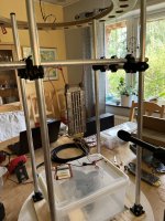
All planars have 1.5 mm xmax unless the last test which uses 2 mm.
First polars 0-90:
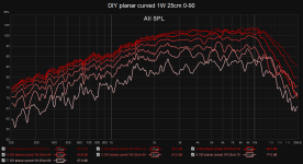
Looks amazing, no ugly peaks at all. I think I can improve it somewhat with some wool covering the outer holes but even if I don't it would be good enough for my target goal. So I am quite pleased with the result!
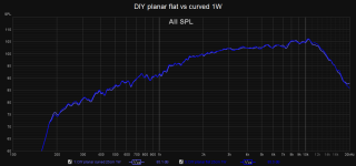
And next is to compare 1W efficiency:
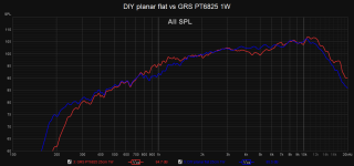
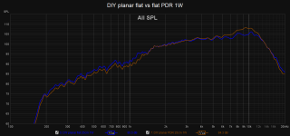
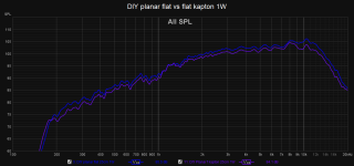
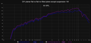
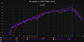
And distortion level matched to 90 dB:
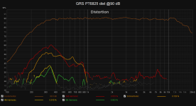
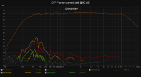
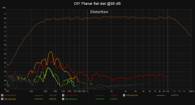
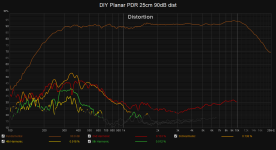
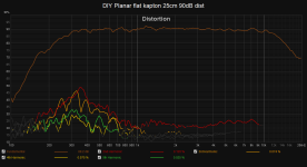
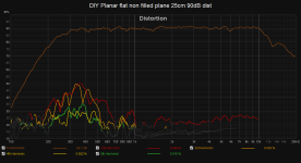
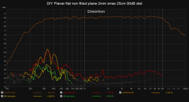
Conclusions:

All planars have 1.5 mm xmax unless the last test which uses 2 mm.
First polars 0-90:

Looks amazing, no ugly peaks at all. I think I can improve it somewhat with some wool covering the outer holes but even if I don't it would be good enough for my target goal. So I am quite pleased with the result!
And next is to compare 1W efficiency:


And distortion level matched to 90 dB:


Conclusions:
- The DIY planars hare superior distortion performance vs the GRS 6825. I am very pleased! Crossing low at 300-400 hz shouldn't be a problem with the full length planar.
- Curved vs flat steel plates measure within margin of error, so I can go forward with curved steel plates for the full length planar.
- PDR exposed outer holes is a dumb idea, I won't investigate further. It doesn't improve low frequency efficiency and distortion, if anything it does the opposite.
- The kapton membrane has lower efficiency but less distortion. It is slightly heavier though. I don't have my high precision scales but when weighing it rounds up to 2 gram where the mylar rounds to 1 gram. It feels heavier too so the measurement makes sense. The reduction in distortion is probably just because of the increased weight.
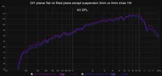
- The membrane with 30 um aluminium is stiff enough that I don't need a completely filled plane, with less undriven alu the efficiency is 2 dB higher without increasing distortion. The efficiency gain is even higher at high fequencies interestingly enough.
- Bumping the xmax from 3 mm to 4 mm reduces efficiency by 1.2 dB but does not impact distortion performance. I will probably continue with 3 mm xmax since I don't expect to push the driver so close to the limit.
Ok.Exactly that one yes! The numbers on the bottom range from 0 to 10, where 10 is 100% of the blade depth. So I twisted it 20% of the distance in between two numbers. I used 120 um which worked well with my mat and material thickness.
Great performance of both you and your planars!
I reckon you get distortion levels that are even lower than the noise level?
I reckon you get distortion levels that are even lower than the noise level?
Great performance of both you and your planars!
I reckon you get distortion levels that are even lower than the noise level?
Thank you 🙂
And yes, it does look like that such low distortion levels are achievable.
I've been thinking more about how the kapton is so heavy. I did get kapton tape with pre applied silicone adhesive since it was cheaper than without. So the kapton membrane has both glue on the kapton and the aluminum + talcum powder to make the exposed glue not sticky. I'm thinking it could be worth trying to remove the silicone adhesive with degreaser or maybe even a dedicated silicone remover.
Could be worth trying say next weekend and then compare the weight of talcum powdered kapton vs glue removed kapton vs mylar.
Although I might not need the extra temperature resistance of the kapton since the drier will be so long. Based on the efficiency above I reckon I will at most push 20 W and that will net me 103-106 dB @ 1m. And even then don't really listen that loud but mostly want it to be able to handle high peaks without much distortion.
But the mylar + my thick aluminum can probably handle far more than that, probably in the hundreds for the full length driver. It would be interesting to do a destructive test... Say I push 20+ W continously through the current test driver and see how much it can handle before it fails. Maybe even run the signal for a few minutes and the use an IR thermometer and see how hot the aluminum gets.
Last edited:
"The reduction in distortion is probably just because of the increased weight."
Weight is always an enemy on a transducer. If you can reduce weight but keep other properties, distortion will be reduced. Not the opposite.
Weight is always an enemy on a transducer. If you can reduce weight but keep other properties, distortion will be reduced. Not the opposite.
"The reduction in distortion is probably just because of the increased weight."
Weight is always an enemy on a transducer. If you can reduce weight but keep other properties, distortion will be reduced. Not the opposite.
Interesting.
I decided that trying to de-adhesive the kapton would be annoying so I placed an order for 12 um kapton film without adhesive. When it arrives I'll re-test and see if see if the efficiency is bumped to same as the mylar, and if the distortion is still slightly lower.
Although to be honest I consider the distortion difference pretty minor in the mylar vs kapton membrane. The main benefit to me would be the temperature stability. I will spend so much time building the drivers so I want them to be rugged and last. I even read nightmare fuel somewhere of how a mylar membrane melted just from being cooked in the sun for too long. Of course I will cover the speaker in fabric but still, generous safety margins are always welcome.
Last edited:
I fried some electrostats in the sun by stripping them from cloth and metal grille. Oops. All organic material will age by time and according to Arrenius for every 10deg C increase in temperature the life time is cut by half. So 30 deg C increase will shorten life time to 12,5% !
Thats why it is important to keep membranes, foam rubber surroundings, electrolytic capacitors, electronics cold and well ventilated. Polymer materials is also negatively affected by humidity.
Thats why it is important to keep membranes, foam rubber surroundings, electrolytic capacitors, electronics cold and well ventilated. Polymer materials is also negatively affected by humidity.
It can also be a result of the damping of the layer of glue."The reduction in distortion is probably just because of the increased weight."
Weight is always an enemy on a transducer. If you can reduce weight but keep other properties, distortion will be reduced. Not the opposite.
Last edited:
It can also be a result of the damping of the layer of glue.
That sounds pretty reasonable.
I wanted to play around more with the kapton. Sadly I have not yet received the kapton roll without adhesive so I decided to play around with plain aluminum foil without adhesive and use only the kapton adhesive instead of kapton + aluminum adhesive. I also got so good results last week during cutting so I reduced the gap width from 0.75 mm down to 0.5 mm. They all cut excellent even with reduced gap width.
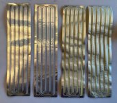
The rightmost is 12 um kapton tape (12 um silicone adhesive) + 20 um plain aluminum foil.
The next to the right is 12 um kapton tape (12 um silicone adhesive) + 30 um plain aluminum foil.
The second to the left is 12 um mylar + 30 um aluminum with ? um adhesive
The leftmost is same as the second leftmost but where I wanted to go crazy and go with 0.3 mm gap width, and it worked!
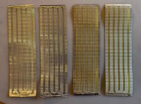
Before I solder the wires and test them I want to weigh them with my 0.01 g resolution scale but I forgot to bring it, but I will have it tomorrow. Then we can see if the kapton membranes are heavier than the mylar. Although this comparison is not entirely fair since none of these are the double glue combo but then again that one is guaranteed to be bad so probably excessive to measure anyway.
It seems that the shop I bought 30 um aluminum foil sent the wrong stuff, they sent 20 um.
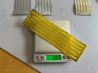
Here is the weight of the "30" um aluminum foil + kapton:
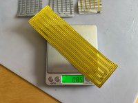
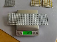
And the actual 20 um aluminum foil + kapton:
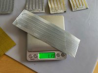
Mylar + 30 um self adhesive aluminum:
For science I dug up the membranes from last week. I did cut off the bottom where I soldered the wires to ensure that the weights are comparable:
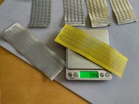
And the kapton double adhesive is super heavy! Probably better to stay at 1 layer of adhesive 😆
I dug up a precision micrometer measurement tool and found out that the acrylic adhesive layer on the self adhesive aluminum is pretty thick. 30 um thick.
Interestingly enough the 12 um mylar + 30 um acrylic glue + 30 um aluminum membrane was still 1.4 dB more efficient than the 12 um kapton + 12 um silicone adhesive + 20 um aluminum foil membrane. The mylar-30um-alu is 0.93 grams, the kapton-20um-alu is 0.84. If we scale up the kapton membrane to 30 um then the weight would be 1.26 g. And 0.93 / 1.26 = 0.738 which in decibel just happens to be -1.3 dB which is pretty close to my -1.4 dB measurement.
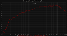
Next weekend I will test the self adhesive 30 um aluminum with non-adhesive kapton. I believe that will bring down the weight in line with the mylar and that the efficiency difference will be negligable.
But another test I want to see how thin I can get the glue layer if I use 3M 77 spray glue. I will email the supplier of the 30 um aluminum foil since they obviously sent the wrong thing, with actual 30 um aluminum then the kapton pre applied 12 um adhesive might yield the lightest membrane overall. Although something worth keeping in mind is that if I use the kapton adhesive or apply my own then the adhesive will be applied over the whole membrane. With the aluminum applied adhesive there will be no adhesive in the gaps, so the overall weight will be less than if applied over the whole membrane. In the end I will just have to test the different combinations and see what works best. A benefit of the self adhesive aluminum foil is that the backing paper and adhesive is extremely smoothly applied, so it is very easy to cut and doesn't self-weed as easy as if I spray the 3M ReMount adhesive where the glue has a larger grain size. That alone might make me go with the self adhesive foil even if is slightly heavier.
Here is the weight of the "30" um aluminum foil + kapton:

And the actual 20 um aluminum foil + kapton:

Mylar + 30 um self adhesive aluminum:

For science I dug up the membranes from last week. I did cut off the bottom where I soldered the wires to ensure that the weights are comparable:


And the kapton double adhesive is super heavy! Probably better to stay at 1 layer of adhesive 😆
I dug up a precision micrometer measurement tool and found out that the acrylic adhesive layer on the self adhesive aluminum is pretty thick. 30 um thick.
Interestingly enough the 12 um mylar + 30 um acrylic glue + 30 um aluminum membrane was still 1.4 dB more efficient than the 12 um kapton + 12 um silicone adhesive + 20 um aluminum foil membrane. The mylar-30um-alu is 0.93 grams, the kapton-20um-alu is 0.84. If we scale up the kapton membrane to 30 um then the weight would be 1.26 g. And 0.93 / 1.26 = 0.738 which in decibel just happens to be -1.3 dB which is pretty close to my -1.4 dB measurement.

Next weekend I will test the self adhesive 30 um aluminum with non-adhesive kapton. I believe that will bring down the weight in line with the mylar and that the efficiency difference will be negligable.
But another test I want to see how thin I can get the glue layer if I use 3M 77 spray glue. I will email the supplier of the 30 um aluminum foil since they obviously sent the wrong thing, with actual 30 um aluminum then the kapton pre applied 12 um adhesive might yield the lightest membrane overall. Although something worth keeping in mind is that if I use the kapton adhesive or apply my own then the adhesive will be applied over the whole membrane. With the aluminum applied adhesive there will be no adhesive in the gaps, so the overall weight will be less than if applied over the whole membrane. In the end I will just have to test the different combinations and see what works best. A benefit of the self adhesive aluminum foil is that the backing paper and adhesive is extremely smoothly applied, so it is very easy to cut and doesn't self-weed as easy as if I spray the 3M ReMount adhesive where the glue has a larger grain size. That alone might make me go with the self adhesive foil even if is slightly heavier.
- Home
- Loudspeakers
- Planars & Exotics
- DIY midtweeter planar, physically curved and shaded to be used in a dipole CBT