


IAIMH…your great pumpkin caught me with just a few sips of coffee this AM.
I didn’t sleep well last night either…then all of a sudden things clicked and out of nowhere the ADHD gods spoke to me…

“COWABUNGA!”
I’d love for my preamp to greet me with that on the TFT each time I fired it up! LOL…pesky copyright laws
I didn’t sleep well last night either…then all of a sudden things clicked and out of nowhere the ADHD gods spoke to me…
“COWABUNGA!”
I’d love for my preamp to greet me with that on the TFT each time I fired it up! LOL…pesky copyright laws
I have a little animation playing in my head.
I used to be good with PowerPoint doing silly little animations and even helped my wife with some presentations. Haven’t done it in years.
Something tells me it’s more difficult than that?
I used to be good with PowerPoint doing silly little animations and even helped my wife with some presentations. Haven’t done it in years.
Something tells me it’s more difficult than that?
animation.....not enough memory in arduino and display controler;
even if, close to gimicks increasing Gremlin's cutiosity
even if, close to gimicks increasing Gremlin's cutiosity
After long and careful deliberation, I have a product improvement suggestion that is in keeping with my adherence to the KISS philosophy in all things.
It has nothing to do with sound quality but is purely esthetic as that is the only arena I feel qualified to hold forth in regarding the Iron Pumpkin.
Enlarge the fierce pumpkin logo 2.5x, then place small, dim, blue LED's in his eyes replacing the bright ones under the Zen Amount knob.
May also serve as an effective gremlin deterrent, not to mention being beyond cowabunga cool.
Well it seems to have taken me about 5 years…but I finally started “working” on my Iron Pumpkin!
Lots of of projects and distractions during that time. I won a set of Babelfish J2 PCBs at the BAF 2019 raffle which led to building a pair of stereo BJ2.
Believe it or not, I think ZMs guidance in the KISS thread was a pretty big contributing factor in my procrastination on this preamp. Once I was able to shoe-horn some Jensen iron in the back of my DCB1 I fell in love with it.
This will probably take me forever to finish, but now I have some motivation in the form of fancy casework on it’s way from Italy.
Our fearless (Greedy Boy) leader currently has my request for a Logic kit in his que.
Since my boards are older and were intended for use with rotary switches I’ll have to start by making some alterations to them so the Logic kit will work properly.
Rather than nag ZM via email I figured I’ll post here in case others might have older boards like me and want to do the same thing.
Also, it always helps to have more than one set of eyes to point out stupid mistakes 😉
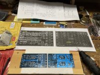
I printed out what I believe is the appropriate version circuit diagrams from post #136.
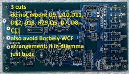
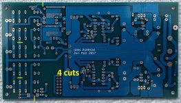
So for now all I had to do is follow the bouncing ball…ZM sent me
some pics of where to start cutting traces.
Buzz buzz buzz went the Dremel…
Lots of of projects and distractions during that time. I won a set of Babelfish J2 PCBs at the BAF 2019 raffle which led to building a pair of stereo BJ2.
Believe it or not, I think ZMs guidance in the KISS thread was a pretty big contributing factor in my procrastination on this preamp. Once I was able to shoe-horn some Jensen iron in the back of my DCB1 I fell in love with it.
This will probably take me forever to finish, but now I have some motivation in the form of fancy casework on it’s way from Italy.
Our fearless (Greedy Boy) leader currently has my request for a Logic kit in his que.
Since my boards are older and were intended for use with rotary switches I’ll have to start by making some alterations to them so the Logic kit will work properly.
Rather than nag ZM via email I figured I’ll post here in case others might have older boards like me and want to do the same thing.
Also, it always helps to have more than one set of eyes to point out stupid mistakes 😉
I printed out what I believe is the appropriate version circuit diagrams from post #136.
So for now all I had to do is follow the bouncing ball…ZM sent me
some pics of where to start cutting traces.
Buzz buzz buzz went the Dremel…
Attachments
Sheesh... I'm a dodo... I've needed to do a little surgery on a few boards over time, and I never thought to use a Dremel. I've used razor blades, and the end-result (albeit effective) usually looks like someone took a chainsaw to the boards.Buzz buzz buzz went the Dremel…
Why can I never get a Mouser order correct? Had a pile of parts in my cart... and... forgot to submit the order. LOL!

Twiddling thumbs until Monday's FedEx delivery...
Twiddling thumbs until Monday's FedEx delivery...

I don’t think we need to go over the benefits of a nice long screw here😉
Looking at those itty bitty NTC on your board…and thinking I don’t gots them😒
@MZM…I was thinking about your decision to turn both channel boards into one big one. I know you commented somewhere on the decision, but can’t remember main reason. Was part of it to have a large ground plane under turtle to help with shielding?
I have some raw copper PCB board I could mount under my turtle. Not sure if it’s worth the effort or if it should be tied to the ground plane of the boards.
no big copper plane at big motherboard
reasons are unification, neater wiring (of everything), simply avoiding plethora of smaller pcbs connected through tiny wires
just chill ......... sound wise - what you have is exactly the same as being on big MoBo
reasons are unification, neater wiring (of everything), simply avoiding plethora of smaller pcbs connected through tiny wires
just chill ......... sound wise - what you have is exactly the same as being on big MoBo
 =😁
=😁


- Home
- Amplifiers
- Pass Labs
- Iron Pumpkin(s) and other smaller vegetable animals