This is the point where I could use a little nudge in the right direction, guys... Does the low voltage mean the transistor(s) are bad, or could it be that the transistors are good but a faulty component or some other condition is causing them to misbehave?
I have been using HTS-3500 (not the mkII) daily for over twenty years to watch TV with no problems at all!
There is a "normal/remote" switch on the back. If the switch is in the "normal" position, you need to press the "ON" button on the front panel to turn on the "SWITCHED" sockets and meter light, and the "TIMED" sockets will turn on after a few seconds.
When the "OFF" button on the front panel is pressed, the "TIMED" socket will turn off immediately, and the "SWITCHED" socket and meter light will turn off after 30 seconds.
Did you test with the rear panel switch in the "NORMAL" position?
https://manualslib.com/ monster_power/hts3500.pdf
Last edited:
@chrisng Yes at first I tested with the switch in both normal and remote modes and neither worked, for obvious reasons. I also tested the toggle switch, due to a couple posts saying that switch sometimes goes bad, but it tested fine.
Thanks for sending pics of your unit, I wouldn't have expected it to be so different from mine. Yours looks like it was better built, too.
If I am seeing correctly, your voltmeter lamp is an axial bulb kind of like this and it's located at the top of the dial? My bulb is missing for some reason, but the soldering pins for it are at the bottom.

@MFRD
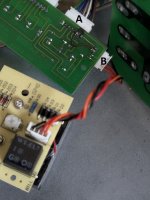
I noticed that mine has two transformers while yours only has one, from the pictures online I see that the MKII model has a board with some diodes and transistors that provide power to some front panel LEDs, are these LEDs lit?
Maybe it also provides power to the HA17339 IC? Can you post a close-up photo of that board?

Yes, it is a filament bulb.If I am seeing correctly, your voltmeter lamp is an axial bulb kind of like this and it's located at the top of the dial?
I noticed that mine has two transformers while yours only has one, from the pictures online I see that the MKII model has a board with some diodes and transistors that provide power to some front panel LEDs, are these LEDs lit?
Maybe it also provides power to the HA17339 IC? Can you post a close-up photo of that board?
Maybe it is a good idea not to compare three* different versions to be able to repair the defective one. The defective one does not seem to have a bulb but a film type maybe gas discharge lamp. I have seen this before as film type behind displays etc. No bulb has been removed, it is logic thinking that has been removed. Just like the voltmeter not registering voltage as there simply wasn't any to register. The voltmeter that was supposedly a short circuit which it was not....
It would not surprise if the backlight just lights up when applying power to the WT-EL7 switcher/regulator. This could simply be tested externally as said before as it is clearly indicate what its input and GND are. It is also least of the problems for now as there is a short circuit or severe overcurrent appearing somewhere preventing power to that lamp circuit and also a defective PSU feeding the timing circuit etc.
*It is OK to focus on the patients left toe but he appears to have a heart condition. Also the patients brother and his wife both seem healthy.
The circuit of the V1.2 version that has the circuit in the red circle is indeed interesting as it could be passing mains voltage to the mainboard. If our patient is built like that that is.
Ah why would I bother? Good luck with the repair.
Last edited:
@jean-paul There is infinite resistance across the backlight pins, would that be expected from a gas discharge lamp? I am not familiar with those.
I am inclined to believe the short circuit condition that blew up the traces was some kind of freak human error. I'm saying this because the visible damage is confined to a single 120Vac path that is isolated from the rest of the circuitry and that goes from the 120V AC bus directly to the voltmeter PCB, which shows no damage and has been working fine along with the voltmeter. So, did some genius put his screwdriver across the 120V bus causing the smaller 120V traces to blow up?
That said, we don't have adequate DC voltage to drive the relays, ICs, etc., i.e. only 2-3V where 12V is expected. Couldn't figure out why voltage is so low at the C1384 emitter yet.
Maybe because the C1384 is shot as there is 16.5V at C and the Zener diode also is OK? Again good luck, the fault finding method is headache inducing. Sorry.
Things maybe are simpler than they seem. As said before one could measure continuity of the wires to L, N and PE of instance. It would not be the first time a wire has broken insulation touching a screw or a sharp chassis corner. Why would a thick person create a short more than once? That isolated 120Vac path is possibly not an isolated path as the device is full of L and N wires/traces and a chassis connected to PE. A single strand of one of the wires touching its neighbor could be such an issue with such inadequate spacing between pins. I would focus on a short of either L to N or L to the 12V circuit. At least measure continuity. If all is OK then repair the 12V PSU. If the backlight then also starts working you'll have gotten a present.
No answers, no help. Maybe numbering questions and suggestions would help. It is now talking to mirror communication.
Last edited:
Pulled the C945 and the C1384 out of the PCB to test them. Both transistors are bad. Hopefully replacements are available locally.
I did some continuity testing throughout the unit and found nothing untoward. Right now I have the entire PCBs assembly out of the chassis but everything is connected as it should be including all grounds etc.
It occurred to me that a short could manifest only when all the boards etc are installed in the chassis and torqued in place. That would explain why I'm not finding anything right now.
It occurred to me that a short could manifest only when all the boards etc are installed in the chassis and torqued in place. That would explain why I'm not finding anything right now.
The local guy didn't have either transistor, or any substitute. Digikey and Mouser say both types are obsolete. But they're available on eBay and Amazon, so I guess that's where I'll go.
Or you use whatever type with the same pinout, current capability and comparable HFe. It is a Darlington circuit for a non audio voltage regulator so no big deal.
BD139-16, can take a heatsink too. Original 2SC1384 is of course good but only when they are affordable.
BD139-16, can take a heatsink too. Original 2SC1384 is of course good but only when they are affordable.
Last edited:
@jean-paul Thanks for the suggestion of BD139-16. C1384 are not expensive, but I'd rather buy current products from legit sources than knockoffs from eBay, when possible. I have a couple questions / comments:
a. STM's data sheet lists BD139, BD139-10 and BD139-16 subtypes but I'm not seeing what the differences are?
b. Is it ok to use two BD139-16 in the Darlington pair, although originally the two transistors in the pair were different types?
c. Conversely, would it be ok to use two C1384 instead of one C1384 and one C945?
d. It looks like BD139-16 has a different pinout than C1384, but they both have the collector in the center so it should be OK
Honestly, without schematics we don't even know for sure what transistors the unit had in it when it left the factory...
I bought it new over twenty years ago and it had C945 and C1384 installed.Honestly, without schematics we don't even know for sure what transistors the unit had in it when it left the factory...
I think @jean-paul needs some sleep due to the time zone difference, maybe I can answer your question and he can correct me if I'm wrong.
A. The difference between BD139, BD139-10 and BD139-16 is their hfe.
https://www.onsemi.com/pdf/datasheet/bd139-d.pdf
b. & c. Although the hfe of C945 is higher, I think you can try it and see if it works, otherwise you can always change to C945 later.
Last edited:
For the 2SC945 I would pick a high hFE type with ECB arrangement. Otherwise one must cross 2 legs which is not desired. If there is no problem with that BC337-40 will probably be OK. Just make sure to put a piece of wire insulation over one of the crossed legs.
If Chris knows a better high hFE 2Nxxxx type alternative please choose that one. ECB is nicer. I am totally unfamiliar with US types but here is a list by Mouser with ECB 2N types:
https://www.mouser.com/datasheet/2/68/lssgp072-36694.pdf
The root cause of the defects is still a mystery. The device will have overvoltage protection probably on the board at the left. Suppose a lightning strike happened far away and it got overvoltage. That could explain what has happened but then the VDRs/MOVs should have functioned. Careful inspection could maybe reveal that. Also check the single mains fuse it has and its value!
Last edited:
Advice: you could make the device safer than the 737 Max design team did by adding a second fuse holder + fuse (if there is none like it appears) to the power transformer so separate fusing of circuits.
Why? : good design should protect wiring/PCB tracks against overcurrent or short circuits. So adequate and adapted fusing to low(er) current circuits. Bonus is that the transformer and the PSU circuit will be somewhat protected too.
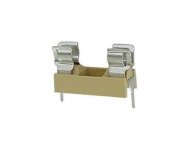
Suggestion: replace jumper J9 or jumper J18 by a 5 x 20 mm PCB mount fuse holder if one can be found with correct pinout/pitch or a wired fuse but that will mean soldering when things go south. Fuse first test value 500 mA Träge.
Challenge is how to do things mechanically sturdy, electrically safe and correct. In case of doubt a chassis mount fuse holder could be placed in a drilled hole in the middle of the removed PCB track between J9 and J10 and mounted upside down. A freshly drilled hole in the bottom cover would then make replacing a fuse possible. Or mount a 5 x 20 mm fuse holder of the solder lug type with solder lugs like the elevated Bulgin FX0360 and screw it to the removed PCB track between J9 an J18 with plastic M3 bolt and nut.
https://docs.rs-online.com/7f61/0900766b8152bdd8.pdf
Why? : good design should protect wiring/PCB tracks against overcurrent or short circuits. So adequate and adapted fusing to low(er) current circuits. Bonus is that the transformer and the PSU circuit will be somewhat protected too.
Suggestion: replace jumper J9 or jumper J18 by a 5 x 20 mm PCB mount fuse holder if one can be found with correct pinout/pitch or a wired fuse but that will mean soldering when things go south. Fuse first test value 500 mA Träge.
Challenge is how to do things mechanically sturdy, electrically safe and correct. In case of doubt a chassis mount fuse holder could be placed in a drilled hole in the middle of the removed PCB track between J9 and J10 and mounted upside down. A freshly drilled hole in the bottom cover would then make replacing a fuse possible. Or mount a 5 x 20 mm fuse holder of the solder lug type with solder lugs like the elevated Bulgin FX0360 and screw it to the removed PCB track between J9 an J18 with plastic M3 bolt and nut.
https://docs.rs-online.com/7f61/0900766b8152bdd8.pdf
Attachments

Last edited by a moderator:
Advice 2: solder an electrically safe and insulated TR5 type fuse holder instead of jumper J19 going to the meter circuit. If a 5 x 20 mm fuse holder fits that would be even better. Start value for testing 50 mA Träge.
Or better: remove both jumpers J19 and J20, cut both the brown and black wire, remove the pins from the connector and take mains voltage carrying wiring away and use a chassis mount fuse holder. You could also make a new 120V mains voltage distribution point with 2 fuse holders mounted on a bracket wired sturdy to that fat PCB tracks carrying mains voltage. Up to you and your electrical creativity!
Mains voltage wiring to fuse holders could be connected to new drilled and soldered Phoenix MKDSN 2 pin 5.08 mm connector blocks directly to the fat mains PCB tracks if the distance between L and N is less than about 5 mm. Choose a 10 mm pitched type for 1.5 mm2 wiring otherwise.
This advice is strong as it were these PCB tracks that burned so things are not designed right. Now both the power transformer and the wiring, the PSU circuit and the meter circuit are fused with replaceable fuses adapted to the low currents flowing there. All not UL listed, OSHA/FCC/NEC/CPSA certified etc. but no more burned PCB tracks and a more safe and repairable device too. Whatever the repair will be, the improved situation wil now also tolerate another failure and/or testing error without catastrophic results.
Last edited:
Because of the time difference and me looking for solutions again a post.
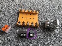
Possible weapons of choice. If they make you happy the odd connector blocks in the circle (we call em short circuit blocks here) are perfect for a safer connection from the boards fat PCB tracks to fuse holders. As the pins are connected not much can go wrong if you use them as intended. Just dril 2 small holes, remove a bit of the solder mask and solder these in. Safer than the jumpers. 2 L wires in one and 2 N wires in the other. Also the screw type connectors of the previous type and fused wire terminals like the grey one in the picture are good.
Have a large quantity of the double pin short circuit 🙂 connectors. If you can use a few let me know.
Attachments
Last edited:
A couple details about safety / protection / etc
a. The unit is protected by a 15A circuit breaker

b. Then the surge suppression board is protected by a 314 style fuse rated 15A 250V

If this unit experienced a massive overvoltage in the past, then all MOVs (being sacrificial components) would have had to be replaced, or the entire SS board for that matter. Presently the SS board is supplying 120V AC to the main board as designed.
Thank you for the suggestions for additional fuse protection. It seems simple enough to implement and definitely worth consideration.
a. The unit is protected by a 15A circuit breaker
b. Then the surge suppression board is protected by a 314 style fuse rated 15A 250V
If this unit experienced a massive overvoltage in the past, then all MOVs (being sacrificial components) would have had to be replaced, or the entire SS board for that matter. Presently the SS board is supplying 120V AC to the main board as designed.
Thank you for the suggestions for additional fuse protection. It seems simple enough to implement and definitely worth consideration.
They survive quite a lot. Is the fuse actually 15A and can you see if it has been replaced?
Whatever the outcome: 120V 15A is quite a lot of energy and short circuit current (a multiple) can be awful high too for thin PCB tracks to 2.54 mm pitched connectors. A 15A fuse or circuit breaker also won’t be of significance when the transformer draws overcurrent. It will burn before the breaker/fuse will react if either of those will react at all.
BTW is is not the unit that is protected by that circuit breaker but more its wiring and its circuit to the load. The whole detailed story I wrote and the defects show that it is inadequately protected itself. The lack of fuses to low current circuits is a design error/safety issue.
Last edited:
Now about those blown traces...
#1 shows the location of the first blowout (and the corresponding burn mark on the bottom of the chassis), and #2 the 2nd blowout:

Below is a close up of #1. Inside the white rectangle, you see that the two very short traces that burned (and were repaired by someone else) are fed straight from the main line voltage bus via jumpers on the other side of the board. The traces terminate at the connector where the black / brown wire pair connects.

From there, the black / brown wire pair travels uninterrupted to a small PCB that supports the status LEDs on the front panel of the unit, which is where blowout #2 took place.
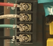
Below is a close up of blowout #2. The black / brown wire pair arrives via connector A and immediately departs via connector B. I found these traces were burned when I got the unit and I fixed them.

From connector B above, the wire pair goes straight to the voltmeter PCB (below). As a reminder, the black voltage regulator thing that feeds the meter lamp is on a different circuit.

The 120V AC path from the main line voltage bus to the voltmeter PCB is as direct as can be. Considering that circuit damage normally occurs at the weakest point between the short and the source, you can see why I was concerned that the voltmeter PCB or the meter itself were at fault - since this is, essentially, the end of that circuit.
#1 shows the location of the first blowout (and the corresponding burn mark on the bottom of the chassis), and #2 the 2nd blowout:
Below is a close up of #1. Inside the white rectangle, you see that the two very short traces that burned (and were repaired by someone else) are fed straight from the main line voltage bus via jumpers on the other side of the board. The traces terminate at the connector where the black / brown wire pair connects.
From there, the black / brown wire pair travels uninterrupted to a small PCB that supports the status LEDs on the front panel of the unit, which is where blowout #2 took place.
Below is a close up of blowout #2. The black / brown wire pair arrives via connector A and immediately departs via connector B. I found these traces were burned when I got the unit and I fixed them.
From connector B above, the wire pair goes straight to the voltmeter PCB (below). As a reminder, the black voltage regulator thing that feeds the meter lamp is on a different circuit.
The 120V AC path from the main line voltage bus to the voltmeter PCB is as direct as can be. Considering that circuit damage normally occurs at the weakest point between the short and the source, you can see why I was concerned that the voltmeter PCB or the meter itself were at fault - since this is, essentially, the end of that circuit.
Attachments
- Home
- Design & Build
- Equipment & Tools
- Troubleshooting Monster Power HTS-3500 MKII conditioner