no more then 10 at 8 - and that is the starting point.Min are 12W fix in classA s
No one tells you what you should do. That is a choice up to you. Steve Jobs used to say "a bag of hurt". I have bought way less hurt for a fraction of A1 2023's price and was satisfied without spending too many hours. Matter of not doing dogmas 🙂
Anyway good luck with the stove. I have to do useful stuff.
Anyway good luck with the stove. I have to do useful stuff.
Last edited:
It's obvious that this product niche is completely overpriced, we don't need to talk about that at all.Well that is a choice up to you. Steve Jobs used to say "a bag of hurt". I have bought less hurt for a fraction of A1 2023's price.
What purchase price do you think is reasonable?
Wrong estimated are 17w , realistic 15w-14Wno more then 10 at 8 - and that is the starting point.
please explain that in detail! please do it!Wrong estimated are 17w , realistic 15w-14W
HBt.

In the meantime,
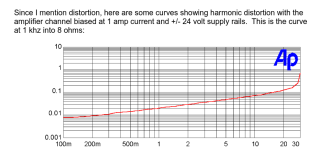
I have taken various measurements on the A1. If you're interested, please read on - but don't call me a troll, because I don't like that.
I maintain that with the typical 0.8Adc quiescent current (typical for every A1), the limit of push-pull A operation is 25.6Vpp.
My DUT had to hold its own in continuous load operation, both channels simultaneously, at 8Ohm +/-j0.
#
Power bandwidth = 60kHz
Maximum power = 30.25Wrms (at the limit of overload)
Gain normal = 36.34dB
Gain direct = 24.15dB
k3 clearly visible in the spectrum from 13.6Vpp (up) at the latest. In the real-time spectral analysis it is very easy to detect when the A1 leaves its true single-ended A mode ..! Up to this point, the A1 is an absolutely awesome amplifier with only k2 in its luggage!
Rise time of a 10kHz square wave (<26Vpp) approx 5µsec
A lower cut-off frequency could not be determined, in my test case of the power bandwidth determination (18Vpp sine wave, both channels under load) the relays suddenly switched off the output at frequencies below 7Hz -> quite unexpected I must admit.
Conclusion:
Still a great little amplifier, which incidentally remains relatively cold under full load in terms of heat sink technology.
@nicoch58
For me, the topic in this thread is exclusively the A1 (with its typical circuit from Tim de Paravincini) and not a circuit from Mr. Pass (which are not unknown to me!).
There is a mains transformer in the current A1 with the data I already mentioned above.
primary: 230Vac /50Hz
secondary: 4 times 19Vac /1.4Aac
Bias current / quiescent current (typical) 0.8Adc
That is all.
What I would like to have (look for) would be the complete documentation for the new A1 -> ServiceManual
Greetings,
HBt.
(mains in Germany are 240Vac /50Hz +/-the usual, permitted fluctuation range)
If MF's power rating should be (caution, absolute speculation):
25 true class A watts, both channels simultaneously under nominal 8 Ohm loads, then the quiescent current should be 1.25Adc (per channel).
You can see how likely this speculation is if you now register the 135Wrms losses that the lid would have to dissipate in heat without control /signal modulation. Provided that the rails do not collapse -> the operating voltage does not collapse.
Ergo:
this scenario and the associated desire for a lot of class A watts is unlikely, even impossible.
Last edited:

An old thread resurrected 5 days ago and already it is drawing attention to itself with 150+ posts in that short period.
Two posts have already been deleted as unhelpful.

Nein. It is 230V +10/-6%. Zwei Hundert und Dreizig Volt.(mains in Germany are 240Vac /50Hz +/-the usual, permitted fluctuation range)
240V +10/-6% would indicate a possible 264V over longer periods of time which would today result in defective lighting, devices etc.
Of course the transition from clean to unreliable energy has made mains voltage going up in time as inverters tend to do that. Certainly when there are areas full of them. Still within the 10%.
Last edited:
Summary:
I came across this thread while searching for information on the current model, a coincidence. My interest in the A1 has been unbroken for decades, so questioning the latest A1 is completely natural. Friends of the A1 would like to know what MF has conjured up here, wouldn't they?
Apart from criticism,
the MF-A1 is an absolutely amazing amplifier, with impeccable sound and features
the
I like my new A1
completes NAD 3020, Acoustic Research A-03 into a formidable trio.
I think that ends the thread for now; the A1 no longer eats woofers in any case, before that the output relay clicks - proven purely by chance in the test a few hours ago.
#
I'm not arguing about the level of light grid voltage in Germany, I can measure and monitor it 24h every day. A few years ago, all the small transformers in my region were replaced with new ones, and since then the 230V fairy tale has been a thing of the past. Incidentally, we've been waiting since 1990 for the day when it's finally ready everywhere. But what's the point of this topic, I'm not a power supply company - just plug in a voltmeter and that's it.
Bye,
HBt.
I came across this thread while searching for information on the current model, a coincidence. My interest in the A1 has been unbroken for decades, so questioning the latest A1 is completely natural. Friends of the A1 would like to know what MF has conjured up here, wouldn't they?
Apart from criticism,
the MF-A1 is an absolutely amazing amplifier, with impeccable sound and features
the
- design is a real eye-catcher
- phono-EQ is second to none
- information in the brochure that it is a 25W class A type is correct if you add the power of both channels as was usual in the past, 12.5Wrms is possible
I like my new A1
completes NAD 3020, Acoustic Research A-03 into a formidable trio.
I think that ends the thread for now; the A1 no longer eats woofers in any case, before that the output relay clicks - proven purely by chance in the test a few hours ago.
#
I'm not arguing about the level of light grid voltage in Germany, I can measure and monitor it 24h every day. A few years ago, all the small transformers in my region were replaced with new ones, and since then the 230V fairy tale has been a thing of the past. Incidentally, we've been waiting since 1990 for the day when it's finally ready everywhere. But what's the point of this topic, I'm not a power supply company - just plug in a voltmeter and that's it.
Bye,
HBt.
Dear jean-paul,
I think it's better if you don't constantly edit, expand and change your posts retrospectively - that distorts the origin.
I would find a supplementary post much, much better - and that is also fairer.
greetings,
HBt.
PS
do you have any insider information on the current model that you would like to share with me?
Addendum to my present A1:
ClippingPower is 2 times 30,25Wrms constantly driven. This means that my rails have to carry a higher voltage than those of the MF laboratory type ... (fits perfectly with the 4.2% higher mains voltage, at my local homebase).
ClippingPower is 2 times 30,25Wrms constantly driven. This means that my rails have to carry a higher voltage than those of the MF laboratory type ... (fits perfectly with the 4.2% higher mains voltage, at my local homebase).
No, fast thinker, short feedback loop so rephrasing and self correction. I'll keep doing that, I am a distorted person.Dear jean-paul,
I think it's better if you don't constantly edit, expand and change your posts retrospectively - that distorts the origin.
I would find a supplementary post much, much better - and that is also fairer.
230V is no fairy tale and the situation was already correctly explained in post 192. That you measure 240V or even sometimes close to or even over 250V is because of solar panels and wind energy and within the 10% tolerance. For energy intended to go the other way i.e. into the grid the voltage of the inverters will go higher than the average mains voltage otherwise not much will happen. Of course higher mains voltage is also beneficial for the energy company too (lower losses) so slowly all things develop to the upper region but no official change to 240V +10/-6% has been announced. 240V as a standard is a fairy tale for now. The plans for the future are 250V in reality. One could choose 250V as a standard and then inverters will do 260V 🙂
You can clearly see that when there is no wind or sun and turbines are feeding the grid the average mains voltage is more close to 230V.
Last edited:
Correction: the plans are to allow 264.5V for a maximum of 10 minutes. For the aforementioned reasons. Officially 230V +15/-6%.
I just ordered a Chinese copy.Could not resist! $350 Australian including delivery and tax.That is about 210 Euro /Us $230.
https://www.aliexpress.com/item/100...13e3cba!12000040472248687!rec!AU!4561885558!X
And https://www.google.com/url?sa=t&sou...wqsBegQIDRAG&usg=AOvVaw0WJvCtSI8yFuqf3GoZ-BqC
https://www.aliexpress.com/item/100...13e3cba!12000040472248687!rec!AU!4561885558!X
And https://www.google.com/url?sa=t&sou...wqsBegQIDRAG&usg=AOvVaw0WJvCtSI8yFuqf3GoZ-BqC
Basically, I don't buy Asian counterfeits or so-called clones - these never-ending stories not only destroy the market, the quality, the service, ... they (also) infinitely increase the mountain of garbage on our planet.
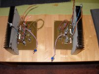
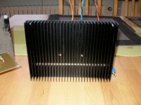
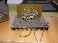
An A1 that barely gets warm to the touch (when in use, of course) can be seen in the attached photos. Unfortunately, I gave away these two modules and even a complete stereo amplifier (my personal version of the A1) 8 years ago - and currently no longer have access to these two incarnations.
The dust comes from our basement, where a few sins still lie dormant on the shelf.
Attachments
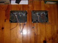
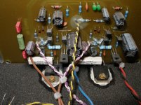

The toggle switch enables a reduction in the AC gain factor and increases the value /amount of the negative feedback.
The 2mm low-current green LEDs prevent the second thermal breakdown; as simple limiters in combination with the band-limiting input filter and the 3k3 seriesresistor, they ensure that the A1 is no longer driven to the rail limit and thus immediately destroyed. They limit gently, round off nicely and, above all, are absolutely symmetrical. No further protective measures are required - the woofer cannot seize up. No pop, no plop... all without an output relay. Absolutely reliable, always safe to use!
I only use TIP2955 & TIP3055 from TI & ST. Unfortunately, my stock is slowly running out, but for me personally, it will be more than enough to last while I wait for the Grim Reaper to come and pick me up.
- Home
- Amplifiers
- Solid State
- 2023 Musical Fidelity A1