
Having built the boards and test assembled I thought I'd check the results I'm getting are to be expected for the high power build:
-Supply voltages: +10.54v and -10.59v
-Voltage across R17 & R18 rising from 0.182 at switch on and settling at 0.207 which puts bias at around 93mA?
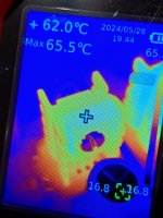
Heatsink temperatures measuring around 62-65 degrees C (ambient is 18)
-Supply voltages: +10.54v and -10.59v
-Voltage across R17 & R18 rising from 0.182 at switch on and settling at 0.207 which puts bias at around 93mA?
Heatsink temperatures measuring around 62-65 degrees C (ambient is 18)
Attachments
Hi @arfadow
Full disclosure: the high power build, which nominally doubles the bias current from 38 to 75 mA, was a paper build on my part, I calculated the values and confirmed with the help of the TLSpice simulation.
I (and TLSpice) neglected to consider the temperature increase. The high temps are changing the transistor properties leading to - not thermal runaway exactly - but an increase in bias current from ~80 mA to ~95 mA as the components warm up.
The solution involves replacing some resistors, moving the values back towards the 38 mA build. Let me dig out the simulation to give you your best option to dial it back a little.
That said +45 above ambient / 65C operating temps are reasonable, there is no particular reason not to use.
The simplest change would be to increase R17-20 from 2.21 back to somewhere in the vicinity of 2.7~3.3 ohms. 2.75 should probably do the trick.
Hi Richard,
Thank you for putting this through a simulation and providing an alternative option so quickly! I have an order going in to Mouser/DigiKey soon so will get a few values to experiment with.
Many thanks!
Thank you for putting this through a simulation and providing an alternative option so quickly! I have an order going in to Mouser/DigiKey soon so will get a few values to experiment with.
Many thanks!
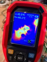
This is all interesting. Glad I visited this thread again. I bought an IR thermometer to test the heatsinks on my high-power build. I was getting readings similar to arfadow's. My solution was to increase the size of the heat sinks and temperatures are now under 50C, closer to 40C. Is there any reason I should change R17-20 as well?
@HaroldHill
That would be entirely optional as the circuit is not optimized for exactly 75 mA bias and 90-95 mA is a reasonable value.
That would be entirely optional as the circuit is not optimized for exactly 75 mA bias and 90-95 mA is a reasonable value.
Hi Richard,
Results from more experimenting with the high power build for different values of R17-20:
2R21>0.207V>93mA>62-65C
2R74>0.202V>74mA>57-60C
3R3 >0.195V>58mA>52-55C
(R17-20>Voltage across R17-20> Bias current>Heatsink temp)
When considering noise, distortion, freq response, linearity etc is there a preference as to which resistor value is optimal?
@arfadow
Thanks for providing the hard data.
Considering that the normal configuration is about 35 mA, I'm inclined to go with the 2R74 resistors at 74 mA which neatly doubles the bias. On the other hand, using 3R3 saves you 5-6C while still providing a hefty kick of almost 60 mA bias.
I think if your headphone impedance is 32 ohms or more 3R3 is the more reasonable option. If you are trying to drive 16 ohms, or some nutty "head speaker" monstrosity then crank it to max - but you might want to install some slightly larger heatsinks.
P.S. I'll update the design reference guide to reflect your finding.
Thanks for the steer on this Richard, for my situation I'll proceed with the 3R3 approach retaining existing heatsinks given I have 25ohm 103dB/mW reasonably efficient planars so nothing monstrous clamped to my head! I can always drop in the 2R74's if I experience anomalies.
I'm curious if anyone is using similar spec headphones with the standard build and what their experience is.
Much appreciated.
I'm curious if anyone is using similar spec headphones with the standard build and what their experience is.
Much appreciated.
Here's my old plot of the output power vs. bias current. The power increase is (I_bias2/I_bias_1)^2 hence doubling the current gives four times more power into low impedance loads below 50 ohms or so. Even 58 mA (3R3) provides a 2x increase over stock, from 60 mW to 150 mW at 25 ohms.

Attachments
Last edited:
Having considered this further, I'm going with 2R74 and have an alternate set of heatsinks on order. It provides the ~75mA bias the high power build is set out to deliver and removes any compromises the 3R3's might impose if I change to headphones that are a little more demanding to drive.
Maybe a little OCD but feels more future proofed.
Maybe a little OCD but feels more future proofed.
This confirms what i was measuring in open air. I measured 48C in open air and 52C in the enclosure +-3C. I did not have an IR thermometer so i had to improvise.down to 45 degrees C
Not the most beautiful thing but its done. Considering that i planned relay volume control, balanced input with relay switching, active DC offset monitoring, VU meter, and remote power switch. Only the relay volume made it and without it was pretty empty inside. Its being powered by a dienoiser reg and surprisingly the 12VA transformer only gets slightly warm after hours of usage. Its still a great sounding amp, powers the 600ohm beyer without issues.


Found where the noise was coming from. The preamp board references the next stage to its local ground. The sapphire is missing the usual input resistor and since the attentuator moved to the preamp board and the connection from input to ground was removed. Added 100k resitor and 2.2nf cap to ground after the 1k resistor and its dead silent now.
@kazuviking
Yeah, that makes sense. I always assumed that the Sapphire board would be placed after a volume control. If not, you need to add a physical resistance of some sort to ground, though it would be unusual if the stage you had placed in front of it didn't have a resistor to ground on the output, which would serve that purpose by default. In short, you'll need some connection between the input side of the Sapphire's capacitor to ground.
Yeah, that makes sense. I always assumed that the Sapphire board would be placed after a volume control. If not, you need to add a physical resistance of some sort to ground, though it would be unusual if the stage you had placed in front of it didn't have a resistor to ground on the output, which would serve that purpose by default. In short, you'll need some connection between the input side of the Sapphire's capacitor to ground.
Sometimes my genius is frightening. I was having thermal runaway issues pretty frequently and i did every single troubleshoot step i could think of. At first i removed the second sapphire board that replaced the line converter board for more gain but it kept happening. Well i thought i used 4.7Ω resistors but no, i used 2.7Ω and increased the supply voltage to 13V. Replaced them with 7Ω ones and it fixed my issue. 221/6.2=31.5x1.17=36.8ma bias, just above the stock config.
Attachments
- Home
- Amplifiers
- Headphone Systems
- RJM Audio Sapphire Desktop Headphone Amplifier