
I feel like 4 PCBs and a 4-gang pot is a bit overboard, have you considered trying an input transformer such as described here?
https://www.jensen-transformers.com/wp-content/uploads/2014/08/an003.pdf
https://www.jensen-transformers.com/wp-content/uploads/2014/08/an003.pdf
Why can the Sapphire not be changed into a symmetric circuit, since it is almost a fully symmetric circuit already? Or just use a high quality transformer for the input. Or - even simpler - just drive the sapphire's inputs with the balanced outputs of the Ayre. This will need a good grounding management.
Thanks for your comments @lohk @itsikhefez
The symmetrical input circuitry of the Sapphire is already spoken for as the input signal goes to one half, the feedback to the other half. It is not a true differential input stage. Even if it were there is still the issue of the volume control, and a SE-BAL inverter circuit would have to be added if it was to be used with SE input signals.
I considered input transformers, but feel they color the sound. I haven't ruled them out entirely, but I'm looking instead for an active circuit that does the same job but is still a cut above a simple opamp. A BAL-SE circuit that is in the same spirit as the Sapphire itself. Ideally one that also has a corresponding SE-BAL topology.
I'll leave this here as a starting point "one box" solution,
INA165x SoundPlus™ High Common-Mode Rejection Line Receivers
The data sheet also shows how you can do it with two buffer stages, one for each input phase, and one op amp setup as a basic differential amplifier.
Those three stages could be implemented with individual opamps, or potentially built as discrete modules.
Hello friends


I'm thinking of making my own boards with power included
I don't know much about electronics and I would need you to help me give your opinion
I upload an image of the schematic and one in 3d of how the board would look
I'm sure there's something wrong and can you help me?
Thank you very much for your attention and patience
@Mandragora By all means. I was working with the free version of EagleCAD that placed limits on the board area. That's the main reason my boards are 8x10 cm. If you've settled on your power supply design and want to do an all-in-one, why not? Keeps things neat and convenient.
For the record, from my point of view, there are good reasons why I wouldn't - even if EagleCAD allowed it.
Mostly, it's the loss of flexibility re. the type of transformer, the diode package, and the placement of the power supply relative to the Sapphire circuit. Everyone has different ideas for what's best, different case geometries, etc, and I need to provide as general a solution as possible. In particular, specifying an exact transformer package when physically speaking there is no need to do so is an nonstarter.
note: I would add another two mounting holes, centered on the long edges of the board, for a total of six. The boards may sag or flex otherwise.
Thank you very much for your answer Richard.
Changing my mind, I plan to build the Emerald boards as well.
If the Emerald and Sapphire boards are put in the same box, can I have interference problems? (power supply in another box)
If I use a single transformer for Emerald and another for Sapphire, do I lose any benefits? (for example the dual mono).
This resistance that is in the Emerald BOM is obsolete, which one can I replace it with?
"R10 - 47R - 791-RC1/4-470JB Kamaya Carbon Comp. carbon composition."
Thank you very much for your attention, surely I will have more questions
Greetings
John
There's no issue putting them in the same box, but as for sharing power supplies, you'll have to approach it trial and error. It should work but I haven't tried.
Yes, I'm afraid carbon composition resistors are facing the sunset of history. I'm using regular metal film for the latest kits. If you can source carbon comp., by all means use them but at the end of the day, regular metal film for this part is not the end of the world.
Yes, I'm afraid carbon composition resistors are facing the sunset of history. I'm using regular metal film for the latest kits. If you can source carbon comp., by all means use them but at the end of the day, regular metal film for this part is not the end of the world.
Thanks Richard
I would put the Sapphire and Emerald boards in a box and in another two transformers, one for Sapphire and the other for Emerald.
When I have images I will upload them.
Thanks for your answers
Greetings
Joan
I would put the Sapphire and Emerald boards in a box and in another two transformers, one for Sapphire and the other for Emerald.
When I have images I will upload them.
Thanks for your answers
Greetings
Joan
Technically, you should be able to power both with a single power supply. If it doesn't work, separate transformers provide a failsafe backup plan.
So i ran into a small issue before i put everything together. I have an old center tapped transformer that is capable of 14V x 800ma, can this power both boards(base config with 37.5ma bias)? If not then which option is better. The 14V 11.2W CT transformer with a 2x12V 10W for the other channel, using two 2x12V 10W transformer or a single 2x12V 16W one for both.
Two 2x12V 10W transformers is ideal, though a 2x12V 16W will be okay. You can use the 28V CT 800 mA is also fine.
I wouldn't use different spec transformers on each channel, and I wouldn't go over 14 V, but other than that there's no particular preference.
I wouldn't use different spec transformers on each channel, and I wouldn't go over 14 V, but other than that there's no particular preference.
Put one board together and don't know how hot should the heatsinks be. I can hold my finger to it for 5-7 seconds before i need to release. The dc offset is 4.7mV. Positive rail 11.47V, negative rail 11.57V. The positive regulator is a bit warmer than the negative.
Both boards working fine. Now all left is to make case and connect everything together. The right board had a bit of buzzing and hum but i think that was my error in the test wiring.

@kazuviking
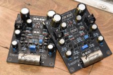
Perhaps it's the test wiring, but it wouldn't surprise me to learn that you've got some poor connections somewhere on the boards.
For starters, R24 is missing from the left board...
In general, though, the poor quality of the soldering throughout is evident from the photo.
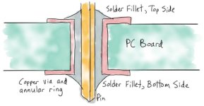
Solder is applied from the bottom side of the board, but the pad should be hot enough that the solder is wicked through the hole to form a little dome of solder on the top side of the board. Look at right pad of R1 of the left board ... that's what they should look like, but almost all of yours look empty - the solder is just covering the hole on the backside, it isn't flowing into the hole because you didn't heat the pad for a few seconds before applying the solder, and/or your soldering iron was simply too weak for the job. Without solder filling the hole, the joint remains mechanically weak and prone to failure.
Staying with R1 on the left board, that resistor is positioned correctly. The body is flat, resting on the top surface of the board. Most of the resistors are "flying" however, the most over-the-top example being R23 on the right board. The resistor should be pulled tight to the board, then held in place by bending out the leads slightly. Once locked in place, solder it and clip the leads. Insert, clamp, solder and clip one resistor at a time until you're comfortable doing several in one batch.
Perhaps it's the test wiring, but it wouldn't surprise me to learn that you've got some poor connections somewhere on the boards.
For starters, R24 is missing from the left board...
In general, though, the poor quality of the soldering throughout is evident from the photo.
Solder is applied from the bottom side of the board, but the pad should be hot enough that the solder is wicked through the hole to form a little dome of solder on the top side of the board. Look at right pad of R1 of the left board ... that's what they should look like, but almost all of yours look empty - the solder is just covering the hole on the backside, it isn't flowing into the hole because you didn't heat the pad for a few seconds before applying the solder, and/or your soldering iron was simply too weak for the job. Without solder filling the hole, the joint remains mechanically weak and prone to failure.
Staying with R1 on the left board, that resistor is positioned correctly. The body is flat, resting on the top surface of the board. Most of the resistors are "flying" however, the most over-the-top example being R23 on the right board. The resistor should be pulled tight to the board, then held in place by bending out the leads slightly. Once locked in place, solder it and clip the leads. Insert, clamp, solder and clip one resistor at a time until you're comfortable doing several in one batch.
Attachments
I realized my mistakes after and redid every single joint after my new soldering iron arrived(cheap chinese 80W one, but oh boi it made things way easier than my old lidl one). R24 was not missing i just put it on the underside for some reason. I did not have a resistor leg bender so i had to improvise. I found the source of the buzzing, it was the cheap input capacitor, after swapping it, now its dead silent.
Still don't have any case to put them into, here i go making a tinfoil wrapped cardboard box.
Thanks for the tips. Currently i'm waiting on BD139/40 to arrive so i can replace the 2SD882-P and 2SB772-P.
Still don't have any case to put them into, here i go making a tinfoil wrapped cardboard box.
Thanks for the tips. Currently i'm waiting on BD139/40 to arrive so i can replace the 2SD882-P and 2SB772-P.
How cheap? 🙂...it was the cheap input capacitor
Under 1€ from a friend. I bought those "audio" film caps years ago to add extra interference filtering into a handmixer, not where you should use them but film is film capacitor.How cheap?
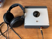
It has been a long road but finally...
Linux Distro (XFCE ubuntu or MX linux) with Pipewire and jamesdsp headphone database for AKG K240 sextett
https://github.com/Audio4Linux/JDSP4Linux
playing through RJM Audio Sapphire Desktop Headphone Amplifier
Majick..!!
Builds fine on any Ubuntu ... (do not use the Flatpak !! permissions are awful )
- Home
- Amplifiers
- Headphone Systems
- RJM Audio Sapphire Desktop Headphone Amplifier