
Hi All-
I have built a few of these wonderful preamps. On my latest adventure I got pretty aggressive and put in 10mf Clarity caps all the way around (and yes it was a tight fit). I have an issue anda question (maybe related). Issue: only one filament of the nutube stays lit. If I turn the preamp unit on, and plug the wall wort into the wall - and then plug the wall wort into the nutube, both filaments lite up initially, but one goes out quickly while the other stays on. I cannot plug the barrel in at any position where the one filament stays lit. Any ideas? The question is I got close to one of the caps with the soldering iron and melted a small portion of it (no interior metal showing). Is this OK? Any degredation?
Thanks for your help.
Does the filament flash on and then off every time the power is turned on?
If it does, maybe there is a flash of hope. Perhaps the resistor in the filament circuit is the wrong value (475 Ohm next to Test Points T5 and T6).
I am assuming a new build. If it is an existing build that was working previously, then as Jim said, damage.
If it does, maybe there is a flash of hope. Perhaps the resistor in the filament circuit is the wrong value (475 Ohm next to Test Points T5 and T6).
I am assuming a new build. If it is an existing build that was working previously, then as Jim said, damage.
Which channel has the problem? Left channel?
I see that the resistor lead and pad on the pcb is very close to the electrolytic capacitor. Check that it is not touching the capacitor and shorting to the case of the capacitor and ground. Also check the solder joints.
What is the voltage across the resistor when powered on?
I see that the resistor lead and pad on the pcb is very close to the electrolytic capacitor. Check that it is not touching the capacitor and shorting to the case of the capacitor and ground. Also check the solder joints.
What is the voltage across the resistor when powered on?
Ok, nothing touching. Will resolder the joints tomorrow. As you are looking at the preamp from the front it is the right side of the nutube. Voltage at T7 is 9.5 and adjustable. T8 is 2.74 and not adjustable. T5 is 10.00 and T6 is 9.98.
That is- the voltage reading across the resistor at T5 is 10 and the voltage across the resistor at T6 is 9.98.
So the right side does not work properly.
If the left side is working properly and the T7 voltage and its adjustability indicate that it is, the voltage at T5 should not be 10V. T5 = 10V is way too high if the left channel is working properly. It should be less than 1V. So there are conflicting voltages.
The right channel also has conflicting voltages. T8 not adjustable and no filament glow indicate the channel is not working properly. However I would not expect T8 to be 2.74V. I would expect it closer to the power supply voltage. Also if the voltage at T6 was 9.98V, that indicated no current flowing through the resistor and filament, yet the voltage across the resistor was also 9.98V. If no current flowed through the resistor the voltage across the resistor should be 0V.
One last voltage comment is that the voltages of 10.00V and 9.98V at the filament circuit of both channels are higher than expected. What is the voltage at Test Point T4?
Another voltage to measure is the voltage across the 332k resistor of each channel. That will show amount of current flowing through the Nutube.
So please confirm the previous measurements. Just to be clear, Test Point voltages are measured with the black probe at Ground and the red probe at the TP. Voltage across a resistor is measured with one probe at one side of the resistor and the other probe at the other side of the resistor.
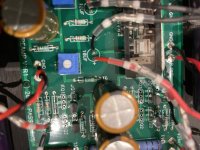
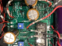
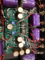
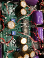
Also please post some clear, focused pictures showing the whole board, with all resistors visible. Take pictures from different angles if necessary so that all resistors and also other components may be seen.
.
If the left side is working properly and the T7 voltage and its adjustability indicate that it is, the voltage at T5 should not be 10V. T5 = 10V is way too high if the left channel is working properly. It should be less than 1V. So there are conflicting voltages.
The right channel also has conflicting voltages. T8 not adjustable and no filament glow indicate the channel is not working properly. However I would not expect T8 to be 2.74V. I would expect it closer to the power supply voltage. Also if the voltage at T6 was 9.98V, that indicated no current flowing through the resistor and filament, yet the voltage across the resistor was also 9.98V. If no current flowed through the resistor the voltage across the resistor should be 0V.
One last voltage comment is that the voltages of 10.00V and 9.98V at the filament circuit of both channels are higher than expected. What is the voltage at Test Point T4?
Another voltage to measure is the voltage across the 332k resistor of each channel. That will show amount of current flowing through the Nutube.
So please confirm the previous measurements. Just to be clear, Test Point voltages are measured with the black probe at Ground and the red probe at the TP. Voltage across a resistor is measured with one probe at one side of the resistor and the other probe at the other side of the resistor.
Also please post some clear, focused pictures showing the whole board, with all resistors visible. Take pictures from different angles if necessary so that all resistors and also other components may be seen.
.
Last edited:
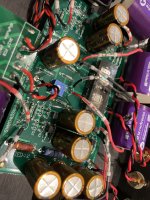
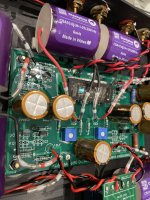
Hi Ben Mah- sorry for the delay, it was grandkids day here. All voltages rechecked and as they were reported before. Test Point T4=10.85v. The left 332 resistor closest to the nutube is 10.96v and the right side is 17.71v. Just a note that I checked all the resistor values before insertion And all were within spec. Pics below, thanks again for the assistance.
Attachments
The 17.7V across the right channel 332k resistor indicates that a large amount of current was flowing through the Nutube right channel even though the filament was not lit. That is not good. Either the tube has a short or something else is happening to cause that.
One final voltage check. Place the meter red probe at the end of the 33.2K resistor that is next to the 10uF capacitor and the black probe at Ground. Power up and adjust the pot. What is the voltage and does it vary when the pot is adjusted? What are the maximum and minimum voltages? If this voltage varies with pot adjustment, then the Nutube is most likely defective.
The 10.85V at T4 is too high. The 9.1V zener diode probably is defective and needs to be replaced. The voltage should be at 9.1V or so. Lower than 9.1V is better than higher than 9.1V as this voltage is applied to the filament circuit and a higher voltage is not good for the filament.
Also have a close look at the Nutube. The filament is a thin strand of wire that runs longitudinally across the tube. Does it appear broken in the right side?
Just for completeness, what is the voltage drop across R1 of both channels? There are two R1 per channel.
Ok,got to it. The nutube filament wire looks to be intact.
The voltage at the end of the 33.2k resistor near the 10mf cap and the potentiometer showed 2.983 as it stood and when adjusting the pot it went from 4.82 to .001 .
On the left channel the voltage drop on R1 is .611 to .001. And on the right channel .608 to .001.
The voltage at the end of the 33.2k resistor near the 10mf cap and the potentiometer showed 2.983 as it stood and when adjusting the pot it went from 4.82 to .001 .
On the left channel the voltage drop on R1 is .611 to .001. And on the right channel .608 to .001.
There are two R1 resistors per channel. Might as well check the voltage drop across those two just for completeness. The two that you have measured are good. The other two should have similar voltage.
The voltage at the end of the 33.2k resistor looks good too.
So far the circuit looks to be functioning properly except for the right channel of the tube itself. A final check would be to have a close look at all of the solder joints. Also have another look at all of the components. Compare all of the capacitors and resistors of the functioning left channel with those of the right channel to make sure that there are no difference between the two channels.
As far as I can tell from the voltage measurements, and if all of the resistors values are correct, the right channel of the Nutube has a short, passing current even though the filament was not lit, and the adjustment of the tube grid voltage had no effect on the tube.
So the right channel of the Nutube looks to be defective.
Also as mentioned previously, the 9.1V zener diode needs to be replaced as the voltage is too high in the one that is installed.
I just rotated the B1 Korg back into my second system, and it's doing its job, adding that tiny bit of second-order harmonic romance I need in that system. It's got the stock electrolytic caps, and reading about people damaging their B1 Korg modifying them gives me pause. I'm hoping to achieve just a little more detail resolution out of these and maybe just change a couple of caps to film caps, not all 3 stages.Hi All-
I have built a few of these wonderful preamps. On my latest adventure I got pretty aggressive and put in 10mf Clarity caps all the way around
Anyone with recommendation for which cap position change will yield the most effect and how low the uF value I can get away with?
Wouldn't the voltage fed to the heater be the biggest threat and not what value caps are being used in the circuit?
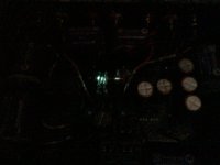
Hi Ben Mah- First, thank you for your assistance. The R1’s checked out OK. I went over the left channel vs the right and all seems well. I went over the solder joints and fixed two that looked a little suspect but no change on the right channel. So, I will order a new nutube and diode for T4. One bit of additional information- as stated previously, upon power-up the right side comes on full for about 1 second then I thought it turned off. However, I happened to look at it in the dark and the right side is “lit” but very dimly. See pic. I don’t know if that changes anything.
Attachments
Sounds like the heater filament is still intact. So maybe the bias voltage for that channel has a problem by way of the trim pot? It is possible. Some of the trim pots that I have used are erratic, so I end up using a 3 turn pot instead. Some that keeps on track where you put it.
So a summary:
This was the voltage at the tube grid so it was adjustable, also indicated that the input buffer circuit was working properly. So no problem with trim pot.
Despite the grid voltage being adjustable, the current through tube was not adjustable, and was constant regardless of the grid voltage, and the current through the right channel tube was much higher than through the left channel tube.
So what I can see is that the right channel tube was conducting, but was not adjustable. It seemed to be shorted, and defective.
Anyone with any ideas? Or a different diagnosis?
The voltage at the end of the 33.2k resistor near the 10mf cap and the potentiometer showed 2.983 as it stood and when adjusting the pot it went from 4.82 to .001 .
This was the voltage at the tube grid so it was adjustable, also indicated that the input buffer circuit was working properly. So no problem with trim pot.
Voltage at T7 is 9.5 and adjustable. T8 is 2.74 and not adjustable.
Adjusting grid voltage did not change the current through the right channel tube. (Note 332 resistor should be 332K)The left 332 resistor closest to the nutube is 10.96v and the right side is 17.71v. Just a note that I checked all the resistor values before insertion And all were within spec.
Despite the grid voltage being adjustable, the current through tube was not adjustable, and was constant regardless of the grid voltage, and the current through the right channel tube was much higher than through the left channel tube.
This indicated current flowed through the right channel filament.That is- the voltage reading across the resistor at T5 is 10 and the voltage across the resistor at T6 is 9.98.
So what I can see is that the right channel tube was conducting, but was not adjustable. It seemed to be shorted, and defective.
Anyone with any ideas? Or a different diagnosis?
Last edited:
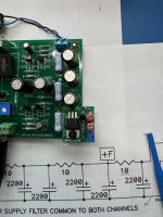
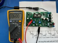
Here's ZM's fancy fix for soft heat start up.
Works like a champ. Beautiful design, easy assembly and installation.
I used a plastic stand off to mount above the board. Fits the space above the removed 9V zener.
I've got 3 boards if anyones interested - PM me.
Thanks ZM and all the contributed to this sweet fix.
Works like a champ. Beautiful design, easy assembly and installation.
I used a plastic stand off to mount above the board. Fits the space above the removed 9V zener.
I've got 3 boards if anyones interested - PM me.
Thanks ZM and all the contributed to this sweet fix.
Attachments
- Home
- Amplifiers
- Pass Labs
- B1 with Korg Triode