The 2 inductors are close enuff, and oriented such that their fields will probably interfere as well.
dave
dave

And the isobaric bring only trouble ah ahhh!!
No, really, I would explore the isobaric better: the two woofers could be coupled back to back ...
No, really, I would explore the isobaric better: the two woofers could be coupled back to back ...
I had to increase a steel laminate coil from 0.8mH to 1.2mH to maintain the 0.8mH value inside a Minimus 7 aluminum cabinet.
So you had 1-(0.8/1.2)=0.333, that is to say circa 33% drop in value due to the aluminium casing.
Let's check here :
According to my post (#99) I have 0.407mH (assuming the spec'ed values of the // coils), and I measure (above) 0.316mH.
So I have 1-(0.316/0.407)=0.223, that is to say circa 23% drop in value due to the aluminium casing.
While it is less than in your case, @wolf_teeth, it is not negligible... To be honest, I expected around 10% (at worse, as often admitted on old RF circuits).
I don't think that in my case, this value drop shows a major audible effect, considering my circuit, but that said, it would be worth to experiment, just to confirm it ! 😉
T
No, really, I would explore the isobaric better: the two woofers could be coupled back to back ...
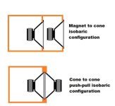
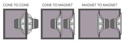
Let's see - Magnet to Magnet vs. Magnet to Cone :
Well, I prefer the Magnet to Cone solution... Why ? In the Magnet to Magnet alternative :
- I don't like too much the back speaker cone fronting the flat surface of the back of the enclosure, at a distance of only 100mm.
- The volume of the isobaric chamber is notably increased, which can be detrimental to the isobaric coupling efficiency of the two speaker.
T
You ideally want to minimize the volume of the coupling camber, and the depth. The depth casues ripplehigher upin frequency and a larger/squisher chamber means less effective acoustic coupling.
dave
dave
Back to back is more stupid! I mean, you have two woofers in opposite direction and you put one in a chamber? Why?
Edit: a sketch!

Edit: a sketch!
Last edited by a moderator:
You ideally want to minimize the volume of the coupling chamber, and the depth. The depth causes ripple higher up in frequency and a larger/squisher chamber means less effective acoustic coupling.
Yes. That's it. This is also one of the reasons why I discarded the slanted panel of my initial design - for the better or the worse :
Slanted, we have 17.32L chamber :
Straight, we have 12.0L chamber :
Taht said, Maybe I should retrace a precise drawing of the slanted version in order to compact it, being very careful that the upper part of the rear speaker cone would never touch the magnet of the front speaker !
Even if I have a limited wood tools equipment, which complicates neatly the execution, it's nonetheless doable. But is it really worth the complication ? Not sure, since this assembly of speakers will work at frequencies under 400Hz. 🤔
T
Last edited:
In my case, the coils were steel laminate types, and more affected. Air cores will be less affected, but still diverge enough to matter. Honestly, 0.4mH to 0.31mH change is quite a bit, and 0.1mH should be audible.So you had 1-(0.8/1.2)=0.333, that is to say circa 33% drop in value due to the aluminium casing.
Let's check here :
View attachment 1335204
According to my post (#99) I have 0.407mH (assuming the spec'ed values of the // coils), and I measure (above) 0.316mH.
So I have 1-(0.316/0.407)=0.223, that is to say circa 23% drop in value due to the aluminium casing.
While it is less than in your case, @wolf_teeth, it is not negligible... To be honest, I expected around 10% (at worse, as often admitted on old RF circuits).
I don't think that in my case, this value drop shows a major audible effect, considering my circuit, but that said, it would be worth to experiment, just to confirm it ! 😉
T
In my case, the coils were steel laminate types, and more affected. Air cores will be less affected, but still diverge enough to matter. Honestly, 0.4mH to 0.31mH change is quite a bit, and 0.1mH should be audible.
Possibly - that's why a test should be interesting for a comparison. That said, since it is for Magneplanar speaker, with wide bandwidth for each element, it's not of a great importance, I think...
T
Have you thought about clamshell arrangement? Definitely the lowest internal volume. And easiest to make. You can recess it inside a little so that magnet does not stick out.Yes. That's it. This is also one of the reasons why I discarded the slanted panel of my initial design - for the better or the worse :
Slanted, we have 17.32L chamber :
View attachment 1335310
Straight, we have 12.0L chamber :
View attachment 1335311
Taht said, Maybe I should retrace a precise drawing of the slanted version in order to compact it, being very careful that the upper part of the rear speaker cone would never touch the magnet of the front speaker !
Even if I have a limited wood tools equipment, which complicates neatly the execution, it's nonetheless doable. But is it really worth the complication ? Not sure, since this assembly of speakers will work at frequencies under 400Hz. 🤔
T
Have you thought about clamshell arrangement? Definitely the lowest internal volume. And easiest to make. You can recess it inside a little so that magnet does not stick out.
@adason, my apologies : what do you mean by "clamshell arrangement" ? 🤔 🤔 🤔
T
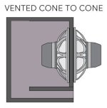
cone to cone
Just use thick wood between to allow membrane travel
Ah, OK : I see - thanks for the explanation @adason !
Unfortunately, by design on my project, one of the speakers must show its cone :
So it's not applicable here...
T
Return to the slanted panel formula 🙂 - instead of straight previously...
Reason : in my last design, the chamber is as compact as possible, but the free air circulation from the cone of the rear Woofer is reduced by the presence of the magnet of the front Woofer.
Obviously, this is not respected in the original configuation retraced below, the yellow lines representing the circular truncated cone defining the free surface available (lower) , i.e. 232cm2 , vs. the free conical areas left between the speaker chassis branches (upper) :

Then I calculated the total free air area left by the chassis at the back of the 12BR70, that is to say the area of four sections of a truncated cone left between the 4 arms of the chassis = 330cm2, not to be confused with Sd=540cm2 at the front of that speaker.
Logically, I should place the rear Woofer at a distance such that this area of 330cm2 exists between its cone and the magnet of the front Woofer - or very close - so the free air circulation could be met...
Since the back of the rear Woofer was then approaching the back panel of the enclosure, why not slant again the rear Woofer panel again ? In fact, that proved a plus on three points :

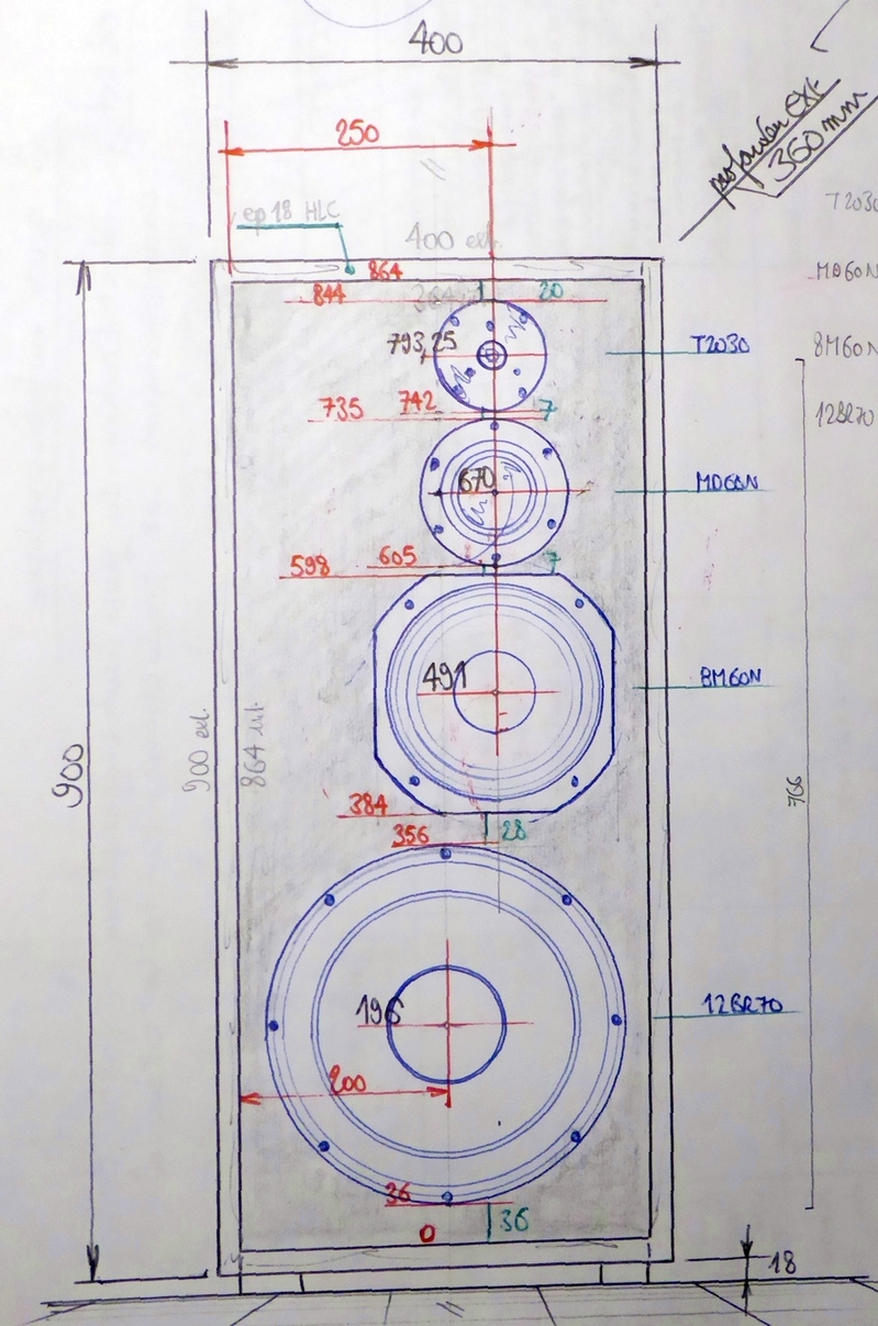
Retraced on my template - external dimensions of the cabinet are unchanged, still HxWxD = 900x400x360mm :

The project is progressing, slowly but surely... 😉
T
Reason : in my last design, the chamber is as compact as possible, but the free air circulation from the cone of the rear Woofer is reduced by the presence of the magnet of the front Woofer.
Obviously, this is not respected in the original configuation retraced below, the yellow lines representing the circular truncated cone defining the free surface available (lower) , i.e. 232cm2 , vs. the free conical areas left between the speaker chassis branches (upper) :
Then I calculated the total free air area left by the chassis at the back of the 12BR70, that is to say the area of four sections of a truncated cone left between the 4 arms of the chassis = 330cm2, not to be confused with Sd=540cm2 at the front of that speaker.
Logically, I should place the rear Woofer at a distance such that this area of 330cm2 exists between its cone and the magnet of the front Woofer - or very close - so the free air circulation could be met...
Since the back of the rear Woofer was then approaching the back panel of the enclosure, why not slant again the rear Woofer panel again ? In fact, that proved a plus on three points :
- better rear speaker clearance from the back panel, as expected.
- larger free air area for the same chamber volume meeting the area condition above, but with straight panel.
- reduction of possible internal resonances, due to the inclined panel.
Retraced on my template - external dimensions of the cabinet are unchanged, still HxWxD = 900x400x360mm :
The project is progressing, slowly but surely... 😉
T
I have a feeling you are overthinking a bit. You insisted on woofers pointing forward, now you placing them on the side. Angled isobaric only complicates construction. You are not reducing internal volume, just making things complicated.Return to the slanted panel formula 🙂 - instead of straight previously...
Reason : in my last design, the chamber is as compact as possible, but the free air circulation from the cone of the rear Woofer is reduced by the presence of the magnet of the front Woofer.
Obviously, this is not respected in the original configuation retraced below, the yellow lines representing the circular truncated cone defining the free surface available (lower) , i.e. 232cm2 , vs. the free conical areas left between the speaker chassis branches (upper) :
View attachment 1336588
Then I calculated the total free air area left by the chassis at the back of the 12BR70, that is to say the area of four sections of a truncated cone left between the 4 arms of the chassis = 330cm2, not to be confused with Sd=540cm2 at the front of that speaker.
Logically, I should place the rear Woofer at a distance such that this area of 330cm2 exists between its cone and the magnet of the front Woofer - or very close - so the free air circulation could be met...
Since the back of the rear Woofer was then approaching the back panel of the enclosure, why not slant again the rear Woofer panel again ? In fact, that proved a plus on three points :
Plus :
- better rear speaker clearance from the back panel, as expected.
The slanted installation represented below - at an angle of 16° - offers a free surface available close to the 330cm2, i.e. 323cm2, which I consider to be close enough to the target value (2% gap) :
- larger free air area for the same chamber volume meeting the area condition above, but with straight panel.
- reduction of possible internal resonances, due to the inclined panel.
View attachment 1336589
Retraced on my template - external dimensions of the cabinet are unchanged, still HxWxD = 900x400x360mm :
View attachment 1336590
The project is progressing, slowly but surely... 😉
T
Last edited by a moderator:
I have a feeling you are overthinking a bit. You insisted on woofers pointing forward, now you placing them on the side. Angled isobaric only complicates construction. You are not reducing internal volume, just making things complicated.
No lateral speaker. This is a cut side view. Nothing complicated if your read the schematic... Correctly.
Yes, the simplest would to buy a headphone set at the next supermarket...
T
I would say , if it has to be angled, let the frontal one be inclined. And adjust the other drivers in a panoramic manner. That means probably more difficulties in design & construction, so it will trashed.
Personally, I've found a Lenard depliant yesterday on my HD, so my decision is firm: trash the isobaric and go BIG! Ah ah ah
Personally, I've found a Lenard depliant yesterday on my HD, so my decision is firm: trash the isobaric and go BIG! Ah ah ah
I would say , if it has to be angled, let the frontal one be inclined. And adjust the other drivers in a panoramic manner. That means probably more difficulties in design & construction, so it will trashed.
Personally, I've found a Lenard depliant yesterday on my HD, so my decision is firm: trash the isobaric and go BIG! Ah ah ah
I hate the trollers : if you are not interested by the subject, simply go away... Welcome to my list of ignored ! 🙂
T
- Home
- Loudspeakers
- Multi-Way
- ISOBARIC sealed enclosure... Any experiences? Any advantages?