Probably part of the reason there distortion numbers aren't great.Nevertheless most commercial Amps have much lower bias current to avoid high power usage and high temperatures.
I've found bias can be run down to about 18mV with no real issues. But distortion increases rapidly below 15mV. My recommendations would be to stick with the numbers in the build guide ~20-22mv across a single emmiter resistor or ~40-44 from TP-101 to TP102 as per point 21.B of the build guide.May be i'm trying to reduce to 15mV/0.22R and checking the effect to THD+N on my usual output requirement
Looking at an impedance curve that's going down to 1.5 ohm. Consider trowing Swiss cheese at them until receiving compensation.Can not reduce to EF-3 cause have to drive a pair of vintage Infinity Kappa 9 speakers with terrible low impedance at some frequencies. (High current)
Nevertheless, it seems everything is relative. I remember from '22 when I was in the process of reverse engineering a Cambridge Audio Azur power amplifier, dropping the project in favor of the Wolverine. Reasons among others being the lower power demand of the later.
I've been reading over the best practices for wiring up amps. A lot of the work seems to be aimed at mitigating the noisy presence of the PSU between the two channels.
Am I wrong?
Why put it there to begin with?
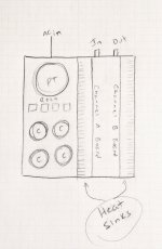
In a stereo amp, would it not be advantageous to keep the PSU (transformers, rectifiers, and capacitors) outside the heatsinks so there's nothing noisy in the area between the two amp boards? I quickly drew up what I mean (attached). It seems a more fool-proof arrangement, noise wise. Everything flows in a tight U.
Does arranging the amp like that cause some other issue I'm missing? Am I failing to conceptualize this correctly?
Am I wrong?
Why put it there to begin with?
In a stereo amp, would it not be advantageous to keep the PSU (transformers, rectifiers, and capacitors) outside the heatsinks so there's nothing noisy in the area between the two amp boards? I quickly drew up what I mean (attached). It seems a more fool-proof arrangement, noise wise. Everything flows in a tight U.
Does arranging the amp like that cause some other issue I'm missing? Am I failing to conceptualize this correctly?
Attachments

It will be interesting to see what you come up with. I played with the idea of a two story cabinet, supply below, amps on top, steel separation between. Haven't worked it out in detail.
That layout isn't uncommon in commercial amps, more-so integrated amps it seems. Be interesting to see noise measurements, mind you it would be hard to truly do a comparison without building both types and testing both.
If its done right as per the instructions in the wiring document then you won't experience any noise issues. How do I know. Because we have done extensive testing on this. Please refer to the image below and you'll see some of the key differences between doing it right and doing it wrong.Why put it there to begin with?
@danieljw youtube video will guide you verbally through this process.
Wiring your amplifier
What your suggesting is fine to. But keep in mind the issues that @mainframe99 and others mentioned. You will also need to follow the guidelines of the document to ensure optimum results.
Attachments

There is lot's of possible variations, GOSS band on toroidal, steel compartment around toroidal, Board Level Shielding of IPS, etc. To expensive for me to try it all out, more a job for a commercial research team, or project on tech university.That layout isn't uncommon in commercial amps, more-so integrated amps it seems. Be interesting to see noise measurements, mind you it would be hard to truly do a comparison without building both types and testing both.
The Board Level Shielding of the IPS might be pretty easy to implement. Works for HF, should work for audio.
If its done right as per the instructions in the wiring document then you won't experience any noise issues...
Thanks Stuart! I hope you didn't infer I doubt the methods that you, the rest of The Wolverine Team, and everyone else have so carefully outlined.
I intended to make a custom chassis anyway. While sketching things out I stuck the PSU in the middle. As I went along I realized I had done that by default. So I asked why, and couldn't come up with an answer besides, "that's where I always see it."
I'm going to give my layout a try. It seems to me I can make the open loop area absolutely tiny.
Will that actually make a difference in noise? Considering the method you outlined already keeps everything out of the loop, probably not. But, I think I can make it look really cool as well. So... 😎 😂
If you're doing custom chassis and want to really minimize noise, consider monoblocks too.
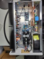
This is my mono amp and I cannot hear any noise at the tweeter.
I am using Garethllywelyn PCB’s for the bridges and ground lifts.
I am using Garethllywelyn PCB’s for the bridges and ground lifts.
Attachments
Boards recieved.
Thank very much to all, They look great, I love the matte black and gold.Would it be possible to send me a link to the Bom for the EF3-4 boards.
Best regards
Anthony (UK)
Thank very much to all, They look great, I love the matte black and gold.Would it be possible to send me a link to the Bom for the EF3-4 boards.
Best regards
Anthony (UK)
A quick search of this thread does not show anyone using or even asking about Sanken 2SA2223A/2SC6145A?
How would they be as a choice of output transistors?
How would they be as a choice of output transistors?
I would only use them if they are Y rank, but Im not sure if the new ones listed on digikey are. What are you planning for rail voltages?
Profusion PLC has plenty of Y grade. They are excellent outputs. Digikey only has O grade in stock (if any).
I have these and I'm going to use these Sankens in my EF3-4 with +/-65V. I'm currently finishing EF3-3 but with these I'm using MG6631/9411 (18A) as my PS voltages are +/-72V.A quick search of this thread does not show anyone using or even asking about Sanken 2SA2223A/2SC6145A?
How would they be as a choice of output transistors?
- Home
- Amplifiers
- Solid State
- DIY Class A/B Amp The "Wolverine" build thread