Try this: .https://www.head-case.org/forums/search/?&q=5.1k%20resistor%20&search_and_or=orDo you have a link?
Standard stuff for Stax.
Perhaps an unwanted comment for OP, but I'd recommend against going ahead with this project for now. High voltages can (and do) kill, and generally you need to understand about one level higher than necessary at the very least when dealing with safety and life-critical systems. I understand this is diyaudio and not premadeaudio but you would benefit a lot from either buying a commercial CE/UL etc certified system, or at most using an existing design after understanding the risks. I myself am not an expert on electronics safety but I know enough to know that I don't know enough. There's a very good reason there's a warning banner on the tube amps page on this site.
If your headphones are DIY as well there are some risk mitigation options possible (like thick insulating ear cups/pads, metal core headbands with current sensors perhaps? and insulated exteriors, testing a high voltage leak on a test dummy etc), but those come later.
If your headphones are DIY as well there are some risk mitigation options possible (like thick insulating ear cups/pads, metal core headbands with current sensors perhaps? and insulated exteriors, testing a high voltage leak on a test dummy etc), but those come later.

Skimming through these posts I found a number of (inconsistent) statements about the purpose of the 5.1k safety resistors:Try this: .https://www.head-case.org/forums/search/?&q=5.1k%20resistor%20&search_and_or=or
Standard stuff for Stax.
- There are a few posts by @kevin gilmore saying the resistors "prevent death to humans", "protect the headphones", or "protect the diaphragm".
- JimL also says the resistors are to "protect the headphones". He also shines some light on why the 5.1k value is used (to achieve "acceptable damping factor" up to 20 kHz and beyond).
- spritzer (in his unique style...) explains that if there would be short to ground (via the user), the resistors would "take the worst of it".
I feel like I must be missing something. On the one hand, estat headphones have been around for many decades, and I have never heard or read of any real-world incidents related to high-voltage failures. For a long time, established manufacturers like Stax made amplifiers that had no protection at all (at least I don't see any in their circuit diagrams), and only during recent years they added the 5.1k "safety resistors". Still they are allowed to market their products with a CE mark (or equivalent). Again, I am sure they are not stupid and have thought about operational safety a lot, and I guess they actually are safe. On the other hand, it's quite obvious that 5.1k resistors alone can't provide sufficient current limiting to protect the user if the high-voltage supply is shorted to the ouput, and the faulty output is accidentally grounded through the user. Maybe I am just exaggerating by making up a chain of unlikely events, but maybe I am also missing something fundamental.
Electrical safety cannot be judged simply by studying the schematics.
The commercial products will have proper insulation that is not detailed in the ciruit diagrams.
You have to inspect physically.
The commercial products will have proper insulation that is not detailed in the ciruit diagrams.
You have to inspect physically.
Skimming through these posts I found a number of (inconsistent) statements ...
Good analysis.
A few more points: Gilmore is the guy behind the fully published "Blue Hawaii" ES HP amp, a trustworthy person. spritzer builds and sells the BH and other amps, in the multi K$ range.
Regarding the value of the safety resistor, it also depends on whether or not you output stage is allowed to pump all of the theoretical 88mA into the victim's head. Normally, a fraction of that should suffice for listening. Also worthy of consideration is the fact it's a lopass filter with the capacitance of the transducer.
Regarding the way the HP is built, I can only speak of what I know, the Jecklin: the cells are pretty standard, and the frame is made of PVC that sort of wrap around the cells, with additional thin sheets of foam outside and inside. It looks pretty safe to me, and I'm even tempted to remove these to get additional transparency, like my Quad ESL57. Maybe someday...
DC vs ACThese guys are not stupid and surely are aware of the fact that with a typical B+ of maybe 450 VDC shorted to ground via a 5.1k resistor, the current would be limited to 450 V / 5100 Ohm = 88 mA (assuming negligible body resistance for a lack of a better assumption). Given the previous discussion, that's too much if it persists for more than a small fraction of a second.
https://electricalinstallationservices.co.uk/is-dc-current-dangerous/
Effects of DC on human body
https://iopscience.iop.org/article/10.1088/1755-1315/108/5/052094/pdf
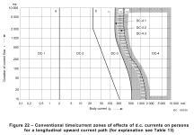
@chrisng Thanks for these links, which point out that current limits for the various physiological effects are higher for DC than for AC. The IOP paper refers to IEC TS 60479-1, which has a lot of useful information (IEC wants a lot of money for the document, but Google found me a free copy). Fig. 22 and Tab. 13 of this document provide a most useful overview of the DC effects on the human body (attached). You'll see that below approx. 130 mA, no irreversible effects or organic damage are expected. A 5.1k "safety resistor" will achieve that limit for DC voltages below 660 V (or higher if the non-zero body resistance is taken into account).
Attachments

Pickering has very low capacitance 1.5kV reed relays, 131 serie.
Since electrostatic headphones use 4 wires (balanced drive, stereo) it would be nice to use a relay with four switches, or maybe two relays with two switches each. 4x single-switch releays would also work, but would consume more space and money.
I think the driving circuit for the relay coil(s) should probably be galvanically separated from the amp output / headphone. I'd use 4x current sensing resistor in series with the amp outputs and link the voltages across these resistors via optocouplers to a low-pass. Once the voltage sensing goes high for longer than a few milliseconds, the coils of the relays should be energized (and kept in this state through a latching circuit) to disconnect the headphones from the amplifier. This would require a normally closed relay.
Also, to run the relay off an existing tube heater supply (typically 6.3 V), a coil voltage of 6.3 V or less would be needed.
The Pickering 131 have one switch only, and they are normally open. I looked for alternatives and found the Standex/Meder BE05-2B-85 type (https://standexelectronics.com/view...p-content/uploads/datasheet_reed_relay_BE.pdf ). However, I can't find any suppliers for these. Any ideas or suggestions for alternatives?
@chrisng Thanks for these links, which point out that current limits for the various physiological effects are higher for DC than for AC.
They are, but you could also get a shock when the amplifier is in perfect working order but the headphone's insulation is not. That will be an AC shock then.
one reason why tasers are lethal is that a currrent through the heart (when aiming close below your left arm) can trigger a ventricular fibrillation of the heart.
We always used a 9V battery connected to electrodes in the heart to trigger VF, while we were doing defibrillation studies. So no, tasers are not harmless.
We always used a 9V battery connected to electrodes in the heart to trigger VF, while we were doing defibrillation studies. So no, tasers are not harmless.
True. So far I was mostly considering what happens if the amp fails with high-voltage DC power shorted to output and the user would get in contact with it somehow. I was looking at this from the perspecive of a fault happening in the amp....you could also get a shock when the amplifier is in perfect working order but the headphone's insulation is not. That will be an AC shock then.
I feel it shouldn't be impossible to extend protection to the AC/audio domain as well. There are some differences between normal audio playback and a fault condition where the AC/audio signal is grounded through the user:
- If protection should also work for AC/audio coming from an amp in perfect working order, some extra thought would need to go into the detection of such situations. Again, I think there is a line between the AC/audio current levels needed for audio playback (10 mA peak or so) and a reasonable safety limit (for example "30 mA for less than 500 ms").
- Also, the AC currents for proper AC/audio output will be high only at treble frequencies, where the headphone impedance is much lower than at midrange or even bass frequencies (see here). For example, I don'see how the AC current could be higher than 1 mA or so at frequencies below 100 Hz for normal audio playback, even at ear-bleeding volume levels. A fault current would be much higher, because the human body impedance is more resistive than an electrostatic headphone.
[ THE NUMBERS IN THIS POST ONLY SERVE TO ILLUSTRATE MY THOUGHTS -- THEY MAY NOT BE A SUITABLE CHOICE FOR IMPLEMENTATION OF A PROTECTION DEVICE ]
Yes, only one normally opent contact, thats why i suggested it, 2 relays, each coil monitoring the dc current of each amplifier channel. Under normal operation the currents hits a certain maximun at wich the relay would still be off, but during an instance where an adjustable limit is exceeded (because additional current finds somehow a way flowing through a person) the relay would switch on and the conthe contacts close, shorting the ps, discharging the caps and eventually blowing a fuse. Will take a few ms but should be quick enough to prevent lethal danger. The advantages are, easy to implement and possible welded relay contacts are no issue. Also, a suitable rated fuse on the transformer primary will have more easely obtainable ratings than something on the hv sideThe Pickering 131 have one switch only, and they are normally open.
Nice and simple. However:...coil monitoring the dc current of each amplifier channel. Under normal operation the currents hits a certain maximun at wich the relay would still be off, but during an instance where an adjustable limit is exceeded (because additional current finds somehow a way flowing through a person) the relay would switch on and the conthe contacts close...
- The relays would only activate with the fault current flowing in one direction, whereas they would not activate with the current in the other direction. We can't know if the output shorts to positive or negative rail.
- I'd prefer to drive the relays with a well defined voltage/current to make sure the activate cleanly.
- I think that if one output fails, the others will likely follow. If a fault is detected in one of the four output lines (estats use stereo bipolar outputs), all outputs should go into protection mode at the same time.
That's an interesting point I didn't think of. Using the relay in series with the output requires the switch to open reliably in case of a fault, and that won't work if the contacts are stuck. I have seen more than one relay with the contacts closed forever... if the relay would just connect a faulty output to earth/chassis instead, the contacts would start at open position. Once the switch is closed, the fault current is diverted away from the user, and will be limited by the "safety resistors" upstream of the relay switches. Worst case would be that the relay contacts get welded together when switching the high voltage, and the relay would need to be replaced while repairing the broken amp.The advantages are ... possible welded relay contacts are no issue.
Likely does, but maybe not audible.using 12v car lamp for save tweeter add distortion too???
mbrennwa :
.....the contacts would start at open position. Once the switch is closed, the fault current is diverted away from the user, and will be limited by the "safety resistors" upstream of the relay switches. Worst case would be that the relay contacts get welded together when switching the high voltage, and the relay would need to be replaced while repairing the broken amp.
Thats the idea, preventing the worst case by shorting the powersupply, discharging all caps and blowing the fuse on the primary of the powersupply.
The only drawback i see, circuit dependend, you may need a total of 4 relays.
Sensitivity of the relays could easely be adjusted with a paralell resistor...or enhanced by some clever circuitry...but that again...increased parts count amount to increased...
But you know all that 😉
A very crude built overcurrent relay once safed me when my thunb first got zapped by12kVdc (my arm flew back i thougth it got ripped off) and next my knee got too close to one of the 3 transformers hv-windings whilst standing in a pool of water and seeing myself burning.
Luckely i got away with a red swollen thumb and a hole in my knee.
I can tell you, without that overcurrent relay, i would at least have lost my foot.
Offcourse the control voltage parts where mounted back on the sidewall close to the hv rectifier when they should be reachable without getting close to the 12kV of a 80kW rf-heater.
And offcourse the high voltage came on by itself... WHEN IT SOULD NOT (do too, to me unknown, "improvements" made by the factories "clever" electrician)
And offcourse the circuit diagram also knew nothing of this...
And offcourse the clip from the hv-shorting cord was missing...
And offcourse i should have...
And offcourse, even working on a control circuit with 230V migth be unhealthy whilst standing on a concrete floor in a pool of water.
But, hey, it could be thats what saved me, otherwise the over current relay, set at 7A, would never had tripped (gladly, the actual operating operating current was close enough to the tripping point, so my leg got torched by maybe 1-2 amps at most).
Anyway, i thinck taking out the ps and discharging the caps as quick as possible by a controlled shortcut is really needed, when there is a possibility of lethal current passing through your head.
Last edited:
Oh @gorgon53 that sounds awful!
Your point about shorting a faulty output to ground/earth to discharge the stuff upstream is well taken. In an estat amp, the shorting could easily be done through the "5.1k safety resistors", which would help to do this in a controlled way by limiting the current to a sane value.
Your point about shorting a faulty output to ground/earth to discharge the stuff upstream is well taken. In an estat amp, the shorting could easily be done through the "5.1k safety resistors", which would help to do this in a controlled way by limiting the current to a sane value.
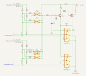
Here's a concept / idea for a possible protection circuit. I have not tested this, so it's really just an idea. Here's how the circuit in the attachment is supposed to work:
During normal operation (no fault), the left amplifier output is fed to the headphones through R1+R3 and R2+R4 (the right output works the same, so I'll just skip it here). The peak audio current into the headphones will be less than 20 mA even with very loud audio playback, so the voltage across R3 and R4 will remain < 1 V, and the LEDs in the optocouplers will remain off.
If there's a fault with the headphone shorting to ground (for example through the user), the current will be limited by the "safety resistors" R1 and R3 (5.1 kOhm each). If the peak voltage from the amp is 500 V, the peak current through R1 and R3 will always be limited to < 100 mA (yes, the power supply of the amplifier may limit the current to a lower value, but let's not rely on this). This current limiting through R1 and R3 works without any delay and provides a useful first step of protection.
Once the current to the headphones exceeds 20 mA, the voltage across R3 or R4 exceeds 1 V, and one of the LEDs of the corresponding optocoupler will turn on (each optocoupler uses two antiparallel LEDs, so the direction of the current does not matter). The optocoupler output will turn on, and C1 will be charged via R7. At the same time, C1 is also discharged to GND via R8 and the relay coils. If the fault current keeps the optocoupler on for longer than about 50 ms (time constant of R7/R8 and C1), the C1 voltage will be large enough to turn on Q2. The resulting voltage drop across R9 will turn on Q1, which activates the relays. The voltage drop across the relay coils is linked to the Base of Q2 via R8. This latches Q2, Q1 and the relay switches to the "on" stage until power is removed. Note that this latching circuit can be triggered both during normal operation of the amplifier, or if there's fault shorting the B+ or B- rails to the amplifier output. The only requirement to activate the relays is that the current to/from the headphones exceeds 20 mA for a couple of milliseconds.
With the relays activated, the headphone output is connected to Earth, which (i) diverts the fault current away from the user/listener and (ii) helps discharging the power supply before a fuse or the "safety resistors" blow up.
It would be interesting what you guys think. Would this work? Would it work well? Did I miss something? Thoughts, ideas, comments?
Attachments
- Home
- Design & Build
- Parts
- What's wrong with fuses (in audio signal)?