Nice, I have a pair of these drivers in storage crying out for a mate.
8BQ / 800Hz
8BQ / 500HzFaital HF1440, A520G2/T520-36-STD-1
It's a strange driver. I only wonder if this is the current production line. I bought them quite early.
But of course with a little active help, it's otherwise remarkably smooth and clean.
View attachment 1322861
BTW, here's the same driver (and a 65CDN-T) in EXAR550: https://www.diyaudio.com/community/...-design-the-easy-way-ath4.338806/post-7645128

In 80s Sony patented LCP diaphragms, they have good internal damping cleaner CSD. Now popular in headphones. Anyone seen in comp drivers?
BMS 4547ND, anyone? With its ~19mm exit tube it would be a nice match for a waveguide like this (currently in the making):
https://www.diyaudio.com/community/...-design-the-easy-way-ath4.338806/post-7595624
But I assume this is a feature of most of the BMS drivers.
https://www.diyaudio.com/community/...-design-the-easy-way-ath4.338806/post-7595624
But I assume this is a feature of most of the BMS drivers.
Last edited:
I wonder if your EQ here is active or passive, measured or simulated?8BQ / 800Hz
That's a simulation of a DSP processing based on the measured data I posted. You can see how a net gain (filter transfer function) would need to look like to make the listening window flat. To get an information on how low those drivers can actually be used, we would need to see also the real measured distortion.
Last edited:
As Mabat correctly said, I am simulating/calculating the filter+EQ combo that would be required to achieve a flat Listening Window (LW) with the stated cut-off frequency.What does "8BQ" mean? BQ Biquad? 8BQ @ 800 Hz? 8th order HP?
//
I use biquad (bi-quadratic function) because it is convenient and easy. The Flat LW target is just convenient and a good/reasonable reference to design a Xover.
From he bottom right graph (the transfer function EQ TF of the resulting filter) one can have a good idea on the feasibility of the Xover in passive or active configuration, the number of BQ indicates the complexity of the digital filter.
A passive Xover would still have to have that exact transfer function to achieve the same LW + HighPass response.
Some WG+Driver will IMO be unreasonable with a passive Xover.
"8BQ" means I used 8 Biquads, for reference a MiniDSP HD can offer up to (10 + 4)14 BQ per way for EQ + Xover, but advance mode would have to be used.
1 BQ can produce an electric 6dB/oct (1st order) or 12dB/oct (2nd order) HP or LP or 6dB/oct BandPass or a shelf, PEQ, AllPass etc.
I use a combination of all the these to fit the ideal transfer function. For each simulation the number of BQ is stated.
"800Hz" means I am targeting a Xover point at 800Hz @48dB/Oct acoustic with a Q of 0.7 (no overshoot) i.e. Driver + WG + Filter.
The HP target details are irrelevant as it just there to test the feasibility; flat LW + 48dB/Oct acoustic HP should cover a wide range of applications.
I use lowish cut-offs because the transfer function already shows the how much relative strain the driver will submitted to, assuming similar sensitivities.
Example DFM 2535 will be attenuated by 15dB @700Hz to achieve a 600Hz cut-off while the BMS 4554 would be only attenuated by less than 10dB for the same target. This does NOT replace real life measurements but might help deciding between drivers for a particular usage.
I never use more than two HighPass biquads (equivalent to 4th order electric or approximated by two parallel inductors and two series capacitors).
None of them have any name (Butterworth Linkwitz etc.) that is irrelevant too. It would be relevant if the DSP was only capable of text book filters (I would not buy one of those).
Higher cut-off might not simplify the filter much as one would need to provide more attenuation.
Bottom line, what matters is the calculated the transfer function required to achieve the target, it is the same whether a passive or an active Xover is used.
Last edited:
One more point, since the SPL data as no reference the overall gain of the filter may vary i.e. WG+DRV are usually 10/15dB+ more sensitive than the LF driver.
For example if the Faital HF1440 produces 110dB for 2.83V (black line labelled 00deg EQ) and the LF driver 95dB at the same voltage then the filter "master" gain will have to decreased by (95-109 = ) -14dB to achieve flat sum, assuming the gain of the amplifiers are the same for the active version and the passive version will need to add a pad (Resistors in series and parallel).
For example if the Faital HF1440 produces 110dB for 2.83V (black line labelled 00deg EQ) and the LF driver 95dB at the same voltage then the filter "master" gain will have to decreased by (95-109 = ) -14dB to achieve flat sum, assuming the gain of the amplifiers are the same for the active version and the passive version will need to add a pad (Resistors in series and parallel).
I've tried a cap plus DSP but came back to full DSP for comp driver. There is little noise audible close to waveguide.
Single cap is never a good idea. You need resistors to flatten the impedance. Or just the resistors alone.
I always wondered if a headphone amp could drive a 16R compression:
https://www.audiosciencereview.com/forum/index.php?threads/topping-l50-review-headphone-amp.26210/
About 2.5W
Sinad 121dB...

Mind you there is no longer a need for low power amps to get SOTA performance. at affordable price.
https://www.audiosciencereview.com/...topping-la90-discrete-amplifier-review.43756/
https://www.audiosciencereview.com/forum/index.php?threads/topping-l50-review-headphone-amp.26210/
About 2.5W
Sinad 121dB...
Mind you there is no longer a need for low power amps to get SOTA performance. at affordable price.
https://www.audiosciencereview.com/...topping-la90-discrete-amplifier-review.43756/
My finding was that a HP amp cant drive them properly. It took a Hypex Nc400 to get it right with my 16ohm 18sound 1095... go figure...
//
estats=electrostatisc speaker?estats
//
For me ideal amp would be 13" 2K QLED tablet like for car audio, capable of doing 8 channels FIR on the fly and having topping amp end with nice SINAD. Such a tablet now costs 130$ and uses TDA7851, TAS6424QDKQRQ1.

estats=electrostatisc speaker? yes
estats=electrostatisc speaker? yes
Nothing unique with your early production units.Faital HF1440, A520G2/T520-36-STD-1
It's a strange driver. I only wonder if this is the current production line. I bought them quite early.
But of course with a little active help, it's otherwise remarkably smooth and clean.
Most likely excessive clearances around the VC, causing a cavity resonance. Likely a byproduct of sloppy engineering and/or chasing power handling for PA use without caring about the consequence. The issue was well enough modeled and documented soon 50 years ago (in the linked AES paper), without comprehensive simulation programs and engineering software. It has a flaw from the design phase due to bad engineering, that goes straight out to customers as is, which seems to be a more and more common thing these days.
EQ'ing cavity resonances to flat level is.. well each to they're own.
In the TD-2001 Some series resistance tends to fill in the hole, so does a high source impedance amp.
For anyone that has a HF1440 it's worth trying. JMMLC made a writeup on it concerning the 2001 at some point.
Same as the HF10AK, TAD TD-2001 etc.
https://aes2.org/publications/elibrary-page/?id=2932
https://www.dibirama.it/component/c...-1-73-8-ohm-120-wmax.html?catid=22&Itemid=580
Attachments
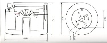
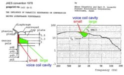
Thanks for you view. I have my doubts about this explanation. As I remember the internals of the HF1440, there's hardly any space around the voice coil.
BTW, did you see this cavity in the DFM-2535?
BTW, did you see this cavity in the DFM-2535?
If a series resistance "fills the hole", what else is it than an EQ? 🙂EQ'ing cavity resonances to flat level is.. well each to they're own.
In the TD-2001 Some series resistance tends to fill in the hole, so does a high source impedance amp.
For anyone that has a HF1440 it's worth trying.
- Home
- Loudspeakers
- Multi-Way
- Acoustic Horn Design – The Easy Way (Ath4)