I think you are going to have to put a DC ammeter in the supply to the amp board as there are no degeneration resistors to measure a voltage. bear in mind the input stages will draw around 15mA or so looking at the schematic, so add that to the output quiescent bias current you want (850mA in the design)

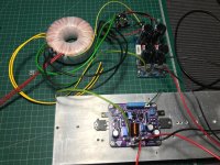
First channel is up and running. No smoke or fire so far, so that's a good sign!
Even on the sacrificial test speaker, the amp sounds very nice and there is no audible hum or hiss whatsoever.
The case I have available is fairly small, but may be just enough to run this amp without getting too hot.
Due to availability, I substituted in MPSA42, MJE 350/340 and the outputs are 2SK2221 and 2SJ352 (Not Exicon, I know, but equivalents).
Setup:
18V rails with CRC on power supply. 160w Toroidal.
7.5 Ohm resistive load.
Measurements with oscilloscope and/or TrueRMS Fluke179 multimeter
Gain:
101mV in, 935mV out = Gain of 9.2
Clip:
9.89V into 7.5 Ohm = 13W output power.
Temperature (5W Sine, at 20 minutes):
Ambient = 18 deg/c
Heatsink / output devices = 65 deg/c
J113 = 53 deg/c
Other devices max = 40 deg/c
PCB = 44 deg/c
Pictures:
Setup:

Clipping looks like this:

1KHz Square wave:

10KHz Square Wave:

Even on the sacrificial test speaker, the amp sounds very nice and there is no audible hum or hiss whatsoever.
The case I have available is fairly small, but may be just enough to run this amp without getting too hot.
Due to availability, I substituted in MPSA42, MJE 350/340 and the outputs are 2SK2221 and 2SJ352 (Not Exicon, I know, but equivalents).
Setup:
18V rails with CRC on power supply. 160w Toroidal.
7.5 Ohm resistive load.
Measurements with oscilloscope and/or TrueRMS Fluke179 multimeter
Gain:
101mV in, 935mV out = Gain of 9.2
Clip:
9.89V into 7.5 Ohm = 13W output power.
Temperature (5W Sine, at 20 minutes):
Ambient = 18 deg/c
Heatsink / output devices = 65 deg/c
J113 = 53 deg/c
Other devices max = 40 deg/c
PCB = 44 deg/c
Pictures:
Setup:
Clipping looks like this:
1KHz Square wave:
10KHz Square Wave:
Nice work so far, what quiescent bias current did you set?
Mine is on the list for 2024, with active rectifier, CRC, reg PSU to feed each channel in dual mono with 2 transformers.
Mine is on the list for 2024, with active rectifier, CRC, reg PSU to feed each channel in dual mono with 2 transformers.
Sounds good.
I set 865mA on the positive rail.
The DC offset I got down to about 2-3 mV with R7. It tends to fluctuate from -2/-3mV to +2/3mV.
I set 865mA on the positive rail.
The DC offset I got down to about 2-3 mV with R7. It tends to fluctuate from -2/-3mV to +2/3mV.
Right on Lineup's spec then. That offset is perfect +/- 3mV around zero.
Hope the second channel is just as good.
Lineup should be pleased with all of that.
You don't want any higher temp on the heatsink, I note you only have 18 degC ambient to give a 47deg C rise on the heatsink to 65 deg C - so it might get a bit toasty on a 30 deg C or more day. So a bigger chassis in the future would be a good upgrade.
I have done some builds with Exicon lateral mosfets. My experience is that 100R for gate stoppers isn't enough. I needed 560R and 680R were necessary (680R for P channel). With higher PSU voltage I even needed to add a compensation (220R + 22p) between D - G of Exicon mosfets.
When I did that, it was rock stable.
I am following this thread.
Regards
When I did that, it was rock stable.
I am following this thread.
Regards
I think once the heatsink is vertical, you might get slightly lower temperatures...
Quiescent current... you may put a series resistor with positive and negative supply and measure voltage drop for an approx idea.
Quiescent current... you may put a series resistor with positive and negative supply and measure voltage drop for an approx idea.
Second channel went fine. A little more temperamental with the DC offset, but centered at around 6-9mV which is well below my personal acceptance level of <50mV.
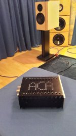
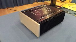
I went ahead and completed the amp with the case I had (need to put the knob on still):

The heatsinks are a tad(!) too small, although the mosfets will happily bask in the heat up to ~140deg/C according to the datasheet at the power levels this amp runs at, and I've only seen ~70deg/c:

Amp sounds great so far! No audible hum, even when packed in tight with the toroid (I did add a little extra screening around the transformer though).
I put in a 3.5mm jack / RCA inputs as option. Thought about putting in a speaker protect module, but didn't want to have another transformer in there taking up space and generating EMI.
Pretty happy with it so far. Going to see how well it lasts and might look at either active cooling to help the puny heatsinks, or consider moving homes to a larger case and repurpose this setup for something that runs cooler...
I might try to get my measurement rig set up for this one to see what kind of harmonic and noise profile it has. It's set up for headphone amps currently.
I went ahead and completed the amp with the case I had (need to put the knob on still):
The heatsinks are a tad(!) too small, although the mosfets will happily bask in the heat up to ~140deg/C according to the datasheet at the power levels this amp runs at, and I've only seen ~70deg/c:
Amp sounds great so far! No audible hum, even when packed in tight with the toroid (I did add a little extra screening around the transformer though).
I put in a 3.5mm jack / RCA inputs as option. Thought about putting in a speaker protect module, but didn't want to have another transformer in there taking up space and generating EMI.
Pretty happy with it so far. Going to see how well it lasts and might look at either active cooling to help the puny heatsinks, or consider moving homes to a larger case and repurpose this setup for something that runs cooler...
I might try to get my measurement rig set up for this one to see what kind of harmonic and noise profile it has. It's set up for headphone amps currently.
Nice build Avtech 👍
You can try to drill holes in the upper and lower plate as i did in my ACA. this convection helps a lot.
my ACA runs with 24V and 2Ampere each side !-- yes---- the IRF are on its max.
chris
You can try to drill holes in the upper and lower plate as i did in my ACA. this convection helps a lot.
my ACA runs with 24V and 2Ampere each side !-- yes---- the IRF are on its max.
chris
Attachments
I decided to go with active cooling for this one in the end rather than wait for holiday season China shipping and spend time moving it to a new case.
So I 3d printed a couple of housings to fit over the heatsinks at the hottest area and mounted 4 silent 6010 fans:

The fans are wired with a switch to allow for half speed or full speed, simply by putting the fans in parallel or series.
The fans are 24v units running at 18V high and 9V low. I measured ~30dB at 1m with the fans on high. I ran the amp for an hour in 35deg (celcius) ambient with the fans on high and the heatsinks stayed cool and the chassis was warm to the touch (but not overly hot).
The amp sounds great on the test speakers and has behaved well so far.
So I 3d printed a couple of housings to fit over the heatsinks at the hottest area and mounted 4 silent 6010 fans:
The fans are wired with a switch to allow for half speed or full speed, simply by putting the fans in parallel or series.
The fans are 24v units running at 18V high and 9V low. I measured ~30dB at 1m with the fans on high. I ran the amp for an hour in 35deg (celcius) ambient with the fans on high and the heatsinks stayed cool and the chassis was warm to the touch (but not overly hot).
The amp sounds great on the test speakers and has behaved well so far.

Hi,
I've finished assembling my amplifier circuit.
I've finished assembling my amplifier circuit.
- Output mosfets 2sj160-2sk1056
- Supply voltage +-18vdc
- Quiescent current 0,75Amp
Attachments
Hi my friend .First channel is up and running. No smoke or fire so far, so that's a good sign!
Even on the sacrificial test speaker, the amp sounds very nice and there is no audible hum or hiss whatsoever.
The case I have available is fairly small, but may be just enough to run this amp without getting too hot.
Due to availability, I substituted in MPSA42, MJE 350/340 and the outputs are 2SK2221 and 2SJ352 (Not Exicon, I know, but equivalents).
Setup:
18V rails with CRC on power supply. 160w Toroidal.
7.5 Ohm resistive load.
Measurements with oscilloscope and/or TrueRMS Fluke179 multimeter
Gain:
101mV in, 935mV out = Gain of 9.2
Clip:
9.89V into 7.5 Ohm = 13W output power.
Temperature (5W Sine, at 20 minutes):
Ambient = 18 deg/c
Heatsink / output devices = 65 deg/c
J113 = 53 deg/c
Other devices max = 40 deg/c
PCB = 44 deg/c
Pictures:
Setup:
View attachment 1240062
Clipping looks like this:
View attachment 1240057
1KHz Square wave:
View attachment 1240058
10KHz Square Wave:
View attachment 1240059
congrats for your building.
with all respect i think you must raise a little the compensation cap.( these small cracks at vertical line and the litle overshooting in corner ).
- Home
- Amplifiers
- Solid State
- Scope Design: JFET Input EXICON Output 10 Watt Class A