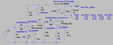
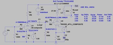
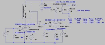
If you have step-up output source, IMHO the best approach to use two stage amplifier (with high impedance input).
As many have recommended: 2P29L or #26, then 4P1L SE (even cathode biased).
As many have recommended: 2P29L or #26, then 4P1L SE (even cathode biased).
I used the Mouser non inductives as filament bias resistor in the 26 and the sound is horrible but if there is no other solution I will buy the 25R.30R filament bias resistor at 650mA filament current gives -about- 21V bias (unnecessarily large) AND dissipates 14W!!!
At least 50W noninductive resistor required with large passive heatsink!
There is no reason to use it.
For example if you want to use 1:4 SUT driven SE (for example spud) with "normal" 2V RMS input, the "required" bias is practically 11-12V.
2V RMS, 2.828V peek - > 4x "gain" -> practically 10V peek due to the losses, so 15-16R (with 650mA filament current) is "enough". The 15R dissipates 7W, so smaller heatsink required.
And the R.C. requiring only 19-20V DC raw supply.
Sample:
View attachment 1317025
p.s.
If you want to eliminate large dissipations (filament bias resistor, R.C. raw supply larger PSU transformer), use simple cathode bias: 300R//470uF in cathode, R.C. feeds the filament points directly). In this case R.C raw supply needs 7-8V DC only.
1-Could be an alternative 22R or 27R for 4P1L as filament bias resistor?
2- Could be better 801A as driver in la e of 26?
2- Could be better 801A as driver in la e of 26?
Last edited:
Everything is possible, just have to think carefully about what the goal is.
Then let's start from the basics. 😴
22R*0.65A= 14.30V
27R*0.65A= 17.55V
Add to this voltages half of filament voltage: 1.05V
The selectable bias voltage curves: 15.35V or 18.6V
Choose the likeable operating point (considering the OPT current too) on bias voltage lines above, from triode curves.
Ale did it for you:

220V, 40.8mA, -17.8V operating point for 4P1L triode SE, 5k6 loadline.
Capable even 1W, 1.1% THD power on primary side (practically about 0.8W on secondary).
It's is close to your choice: 27R filament biased 4P1L, 5k loaded.... if you use 5k:8 transformer and 8R load.
If the load is 18R, the primary transformed impedance is much higher, 11k25.
This loadline requires a bit lower operating point, so practically the -15V bias curve (22R filament bias resistor, 650mA current +half of filament voltage) more usable.
Choose 200V, 35mA, -15V operating point.
The assumed B++ is:
15+200+(Ia*DCR of primary) .... about 220V.
The 22R filament bias resistor is dissipation 10.3W, so at least 50W capable required (+heatsink or forced air cooling).
The V4 R.C. regulator needs 21-22V DC raw supply (0.65A), with -at least 50-70VA capable transformer.
If you want to use #26 as VAS stage, resistor loading or gyrator loading also optional.
Sample:

BTW, at winter (in Spain winter is cold, isn't it? 😁) this small power headamp will help you a lot. 🙂
Heating capacity is excellent: 50-80W/channel.
Then let's start from the basics. 😴
22R*0.65A= 14.30V
27R*0.65A= 17.55V
Add to this voltages half of filament voltage: 1.05V
The selectable bias voltage curves: 15.35V or 18.6V
Choose the likeable operating point (considering the OPT current too) on bias voltage lines above, from triode curves.
Ale did it for you:

220V, 40.8mA, -17.8V operating point for 4P1L triode SE, 5k6 loadline.
Capable even 1W, 1.1% THD power on primary side (practically about 0.8W on secondary).
It's is close to your choice: 27R filament biased 4P1L, 5k loaded.... if you use 5k:8 transformer and 8R load.
If the load is 18R, the primary transformed impedance is much higher, 11k25.
This loadline requires a bit lower operating point, so practically the -15V bias curve (22R filament bias resistor, 650mA current +half of filament voltage) more usable.
Choose 200V, 35mA, -15V operating point.
The assumed B++ is:
15+200+(Ia*DCR of primary) .... about 220V.
The 22R filament bias resistor is dissipation 10.3W, so at least 50W capable required (+heatsink or forced air cooling).
The V4 R.C. regulator needs 21-22V DC raw supply (0.65A), with -at least 50-70VA capable transformer.
If you want to use #26 as VAS stage, resistor loading or gyrator loading also optional.
Sample:

BTW, at winter (in Spain winter is cold, isn't it? 😁) this small power headamp will help you a lot. 🙂
Heating capacity is excellent: 50-80W/channel.
Series-parallel connection (series connected resistors paralleled with series connected resistors) gives protection against overheating.
1/Rres= 1/(22+22) + 1/827+27)
Rres= 24.24 Ohm
Forced air cooling may be necessary.
p.s.
If you have enough large current tolerate OPT (50-60mA), with lesser B++ (about 190V) the paralleled 30R/30W resistors can be used.
Each will dissipate 3.6W, so -if its over the top plate- even some ventilation hole under the resistors would be OK.
Last edited:
Yes I know the series connected resistors paralleled with series connected resistors, the problem is 15€ each resistor.
Last edited:
Thanks Bela, do you believe be safe only one resistor 15R 20W for 7,2W of dissipation?15R filament biased version.
View attachment 1317507
Depends on.
If it's heatsink mountable 20-25W design, without any heatsink 40-50% of power allowed.... at 25 Celsius. At 75C only 30%.
I usually use large Welwyn vitreous enamelled wirewounds (W22...W24).
The 14W W24 at 7W power even 200C hot!
If it's heatsink mountable 20-25W design, without any heatsink 40-50% of power allowed.... at 25 Celsius. At 75C only 30%.
I usually use large Welwyn vitreous enamelled wirewounds (W22...W24).
The 14W W24 at 7W power even 200C hot!
Felipe,
We are talking about robust, high wattage resistors, which are working even all day at desired power, not loudspeaker crossover resistors! 😳
We are talking about robust, high wattage resistors, which are working even all day at desired power, not loudspeaker crossover resistors! 😳
Why 25R?
Is B++ value decided?
Is Ia decided?
The bias (and filament bias resistor value) depends on the former parameters.
See #72 post schematic as sample.
Is B++ value decided?
Is Ia decided?
The bias (and filament bias resistor value) depends on the former parameters.
See #72 post schematic as sample.
- Home
- Amplifiers
- Tubes / Valves
- DHT Headphone amp for HifiMan Edition XS


