You mean LL2765 (or LL2774) from Lundahl?I think the LL2766 gapped for 30mA could be a good start. Secondary is quite flexible, so you could run other impedance headphones as well.
I'm using a LL2774 80mA in my 300B SE. It works well with a -1dB bandwidth from 12Hz to 50KHz.
I really mean the LL2766. It is the smallest OPT from Lundahl, at 750gr. Gapped for 30mA it has 43H, and connection for 6k:16R, which looks great for a 4P1L.

Oops, It seems LL2766 is a relatively new model from Lundahl, which doesn't have a separate datasheet.
It seems great for a 4P1L SE.
https://www.lundahltransformers.com/wp-content/uploads/catalogue/Catalogue_20220822.pdf
Page 201
It seems great for a 4P1L SE.
https://www.lundahltransformers.com/wp-content/uploads/catalogue/Catalogue_20220822.pdf
Page 201
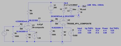
Bela could I use 30R for filament bias? Also I need more information for the filaments PSU TIA.If you can provide 12Vpp (4.24V RMS) on 4P1L power tube grid (Ug), the 100mW output achievable.
See second stage.
View attachment 1278100
p.s.
Small output transformers (Edcor especially) not primary induction champions, so lower -3dB point will be not so low.
Last edited:
What's the goal?Bela could I use 30R for filament bias? Also I need more information for the filaments PSU TIA.
This bias (about -21V) required 235-240V Uak (so anode at about 260V), and 25..30mA current if you want to use linear part of -trioded- characteristic.
The R.C. raw supply -depends of version of regulator- 26...28V.
About 30R for filament bias is because I have on hand & If can use it I don't need to buy the new ones of 25R.
30R filament bias resistor at 650mA filament current gives -about- 21V bias (unnecessarily large) AND dissipates 14W!!!
At least 50W noninductive resistor required with large passive heatsink!
There is no reason to use it.
For example if you want to use 1:4 SUT driven SE (for example spud) with "normal" 2V RMS input, the "required" bias is practically 11-12V.
2V RMS, 2.828V peek - > 4x "gain" -> practically 10V peek due to the losses, so 15-16R (with 650mA filament current) is "enough". The 15R dissipates 7W, so smaller heatsink required.
And the R.C. requiring only 19-20V DC raw supply.
Sample:

p.s.
If you want to eliminate large dissipations (filament bias resistor, R.C. raw supply larger PSU transformer), use simple cathode bias: 300R//470uF in cathode, R.C. feeds the filament points directly). In this case R.C raw supply needs 7-8V DC only.
At least 50W noninductive resistor required with large passive heatsink!
There is no reason to use it.
For example if you want to use 1:4 SUT driven SE (for example spud) with "normal" 2V RMS input, the "required" bias is practically 11-12V.
2V RMS, 2.828V peek - > 4x "gain" -> practically 10V peek due to the losses, so 15-16R (with 650mA filament current) is "enough". The 15R dissipates 7W, so smaller heatsink required.
And the R.C. requiring only 19-20V DC raw supply.
Sample:
p.s.
If you want to eliminate large dissipations (filament bias resistor, R.C. raw supply larger PSU transformer), use simple cathode bias: 300R//470uF in cathode, R.C. feeds the filament points directly). In this case R.C raw supply needs 7-8V DC only.
Last edited:
Mine 26 anode load is Ale Moglia Hybrid mu-follower so I guess could use the 15R filament bias resistor for 4p1l, right?
Once more: what's the goal?
"Gyrator" loaded, (15R) filament biased 4P1L is good VAS stage, with 1:4 SUT it's capable even almost 160Vpp output swing .... but unable to drive 18R headphone.
If you add another appropriate stage for (this, or another suitable) VAS, which is capable for few hundred mW power at 18R load... this can work ... but you should decide what you want.
The goal is that I use gyrator for 26 load in place of 22K resistor of your schematic, the question is can lower resistance of the filament bias resistor for 4p1l ?
Attachments
Last edited:
1.) Using gyrator instead of 22k anode load ... it's possible .... but IMO unnecessary. More expensive, and with 20Vpp swing there is no advantage.
2.) With such B++ and estimated anode current, the bias is definite. Not possible using another filament bias resistor value with this filament current.
2.) With such B++ and estimated anode current, the bias is definite. Not possible using another filament bias resistor value with this filament current.
I have Lundhal LL1660 configured 1-4,5 could be used?30R filament bias resistor at 650mA filament current gives -about- 21V bias (unnecessarily large) AND dissipates 14W!!!
At least 50W noninductive resistor required with large passive heatsink!
There is no reason to use it.
For example if you want to use 1:4 SUT driven SE (for example spud) with "normal" 2V RMS input, the "required" bias is practically 11-12V.
2V RMS, 2.828V peek - > 4x "gain" -> practically 10V peek due to the losses, so 15-16R (with 650mA filament current) is "enough". The 15R dissipates 7W, so smaller heatsink required.
And the R.C. requiring only 19-20V DC raw supply.
Sample:
View attachment 1317025
p.s.
If you want to eliminate large dissipations (filament bias resistor, R.C. raw supply larger PSU transformer), use simple cathode bias: 300R//470uF in cathode, R.C. feeds the filament points directly). In this case R.C raw supply needs 7-8V DC only.
I'm not sure to use this configuration because the noDac output is a 1-7 step-up, so tx to tx???
But I like the idea because I always believe minus is more.
If you want to use 15R as filament bias resistor, must to decrease B++ to -about- 200V.
In this case (15R filament bias resistor, 650mA filament current, V4 R.C.) the R.C. raw supply value is 18-19V.
In this case (15R filament bias resistor, 650mA filament current, V4 R.C.) the R.C. raw supply value is 18-19V.
Thanks, I understand isn't the best 4P1L bias as power amp.If you want to use 15R as filament bias resistor, must to decrease B++ to -about- 200V.
In this case (15R filament bias resistor, 650mA filament current, V4 R.C.) the R.C. raw supply value is 18-19V.
Do you see any problem tx to tx?
- Home
- Amplifiers
- Tubes / Valves
- DHT Headphone amp for HifiMan Edition XS