My setup is smaller and there is some give when forced, but the Klippel NFS seems a bit overkill. But I can imagine that you spend 1000 euro extra on a 100.000 euro machine to be absolutely sure that it is sturdy. Add some 'Deutsche Grundlichkeit' in the mix and you get what it is.
Last edited:
Stiffness I agree with. Reflection within reason should be removed due to the many measurements and averaging.While recuperating from an very fine birthday party with some 50 people, i studied the klippel nfs from a mechanical point of view.
The construction concept is about stiffness without much acoustical reflection.
They made a quite stiff construction for the rotating beam .
Something to take into consideration as well i think.
Will ponder on that
I know over here I have trouble even with mic protrusion from the mic stand when I am measuring tweeters and chasing the fictional bat talk high frequency response. So my guess is that as in REW the steady state reflections will be averaged out. And the microphone arm will definitely be in every measurement.
For those who want a good look at the Klippel NFS hardware: https://www.klippel.de/manuals/docs/hardware/nfshardware/nfshardware.html
What surprises me about the nfs is the stiffness of the arm , whichs is high in particular in vertical direction. Also in relation to stiffness of the microphone beam and also in relation to the central axis.
As if the arm has to be normal to the rotating axis under every measuring condition.
Or, the use of these alu extruded profiles are not so stiff at all.
Or both ;-)
But , jokes aside, the mic distance relativexto the dut can vary significantly when the arm flexes in vertical direction.
I do not know what tolerance limits applies for the mic position, but if we take a arm of 1.5 meters , flex can easily lead to mic position variations of 1 cm or more (my Ball park guess).
Same goes for the rotation bearing btw.
Jan, the vertical stifness can be created fairly easily via compression from either a cable under tension, or a rod held internally and tightened to provide compression on the vertical column. I see wires to distribute the angular moment on the Klippel system. If I could get away from that I would be happy. But they may indeed be necessary.
Thanks Tom for the Klippel details. I had most of this figured out from the other pics posted, but this is perfect!
Thanks Tom for the Klippel details. I had most of this figured out from the other pics posted, but this is perfect!
Yes, the 2 wires not only help to reduce verti cal sag of arm, it also in horizontal direction the angular moment as you state. Still need to understand why so diagonal, but that eill come.
It looks like a make shift construction, that sort of developed along the way, but it works.
So for the shoestring we need to take advantage , not by carbon copy, but by understanding the why and construct our own solution.
Cannot wait to join and contribute, but need to get my GAYA2 purified first.
Addition, after pondering about it, i think the two wire construction is (also) ment to prevent or dampen the swinging of the linear z-axis(holding the mic) when the arm rotates.
A question, if following Kimmo's measurment approach for use in vcad the vertical rotation axis is basically the centerline on the baffle.
With klippel this is not the case, it is more in the middle of the box(enclosure).
How then use the measurements in vcad?
With klippel this is not the case, it is more in the middle of the box(enclosure).
How then use the measurements in vcad?
You can correct the raw measurements for that (up to some point).
But once you've done the fit, you're free to evaluate the function at any place. That can also be the places vcad expects. That would be the preferred way.
But once you've done the fit, you're free to evaluate the function at any place. That can also be the places vcad expects. That would be the preferred way.
VCAD does measurements?A question, if following Kimmo's measurment approach for use in vcad the vertical rotation axis is basically the centerline on the baffle.
With klippel this is not the case, it is more in the middle of the box(enclosure).
How then use the measurements in vcad?
Or still only process measurements?
Processes measurements made with f.i. Arta.VCAD does measurements?
Or still only process measurements?
Kimmo provides procedures for different measurement tools, but wrt to the speaker geometric aspect they are the same
How is the creep deformation on the 3D printed parts? That will either be robust enough or start to slowly move around.
I see a little deformation. I'll keep an eye on it.

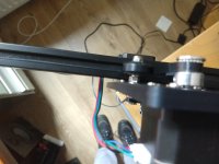
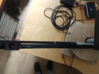
Also the mic boom is not parallel to the main arm:

Somehow the zero-point of the vertical axis moves up. I thought I fixed it by adjusting the counterweight. I also changed the rotation from 0-360 deg to -180 - 180 deg to limit these problems further. If you look at the gifs a few posts back, you can see that 0 and 360 degree don't line up neatly.
It still happens though and the problem is larger than I would like it to be. Of course closed loop steppers would fix this, but I hope I can fix it without having to change the motion interface with my code.
Losing steps is going to be an issue when you measure all day long to get a proper point cloud. So maybe the Closed loop stepper is the only way that is easy to implement. If I remember correctly that has become the best practice with the faster 3D printers as well.
In my potential room I will truly be able to do a 180 degree arc, and then require a rotation of the loudspeaker to do the back side.
I'm thinking of making a few absorptive panels like I specify when we consult for acoustical work. Basically movable like a Chinese changing screen idea. That will quickly lessen the reflections in the midrange and top end and make for some much easier computations that are reliable. I hope.
Does anyone know if these can be connected to the arduino cnc shield and what the difference between CAN and RS385 is?
https://nl.aliexpress.com/item/1005...hEzajoA2&utparam-url=scene:search|query_from:
https://nl.aliexpress.com/item/1005...hEzajoA2&utparam-url=scene:search|query_from:
I don't see how a closed loop stepper will account for mechanical warping in the frame?
Me neither.
The problem is that the z=0 (relative to the frame) creeps up. I found a bug in the software, but it's still not good enough.
Speaking of software... I can try to implement creep correction for the time being.
The problem is that the z=0 (relative to the frame) creeps up. I found a bug in the software, but it's still not good enough.
Speaking of software... I can try to implement creep correction for the time being.
The problem is that the z=0 (relative to the frame) creeps up.
Is it because the rotating platform isn't level over it's travel or something else?
I set zero as the lowest point mechanically possible on the z axis. Mic boom assembly is touching the rotating arm. Then after a full set of measurements for an angle, it should return to z=0 and move to a new angle. It returns to a point that's around 1cm above the original ('mechanical') 0.
- Home
- Design & Build
- Software Tools
- Klippel Near Field Scanner on a Shoestring