I have been using the FQA28N15 based on the recommendation from this thread. I found that the IXTQ26P20P was an excellent match when used in my F5m. I used regular F5 boards from the store with a selected set of components to build my F5m. Power supply is running at +/– 26V and bias is set at 1.5A.
Although this is a different output stage, I believe the IXTQ26P20P will also be a good match in the ZD-25 output stage. I will assemble an amp once a couple pieces of aluminum stock arrive from OnlineMetals.
Although this is a different output stage, I believe the IXTQ26P20P will also be a good match in the ZD-25 output stage. I will assemble an amp once a couple pieces of aluminum stock arrive from OnlineMetals.

It will be interesting to see your results with the IXTQ26P20P. The F5m vs HGF output stages differ in two major ways: common source vs. common drain and degenerated vs. undegenerated.
Impressions of a listener with 3-way speakers
When the GBF is active, then the woofers are full controlled and the low end sounds bone-dry, mids and highs crystal clear but not unpleasant.
I imagine that I already know something similar...and can't resist the temptation to try the HGF with local FB only.
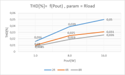
The front end gain set to 12 with R3 = 120k, R4 removed and OPA551 replaced by an OPA604 from my old stash and a quick THD check vs. output load done.
Yes, I did two changes at once thought it would be fine and really it is.
Since two days I have been listening one CD after another, that I know very well.
Now I can hear things for what they really are. When a CD comes to an end, I want to play another one.
This is very emotional, I know, but I am convinced it's a good feeling.
Am I at the point of no return now? Only time knows...
Thanks once more Lynn
When the GBF is active, then the woofers are full controlled and the low end sounds bone-dry, mids and highs crystal clear but not unpleasant.
I imagine that I already know something similar...and can't resist the temptation to try the HGF with local FB only.
The front end gain set to 12 with R3 = 120k, R4 removed and OPA551 replaced by an OPA604 from my old stash and a quick THD check vs. output load done.
Yes, I did two changes at once thought it would be fine and really it is.
Since two days I have been listening one CD after another, that I know very well.
Now I can hear things for what they really are. When a CD comes to an end, I want to play another one.
This is very emotional, I know, but I am convinced it's a good feeling.
Am I at the point of no return now? Only time knows...
Thanks once more Lynn
Attachments
Interesting. Can to hear a difference between the OPA604 and the OPA551 with no global feedback?
Looking at the OPA604 datasheet, the output voltage swing appears to be limited to +/-12V. Looking at the plot, how to do get 16W into an 8R load which requires a +/-16V swing? Maybe I misread the datasheet.
Looking at the OPA604 datasheet, the output voltage swing appears to be limited to +/-12V. Looking at the plot, how to do get 16W into an 8R load which requires a +/-16V swing? Maybe I misread the datasheet.
Last edited:
Datasheet P.4 top right shows THD Vs output voltage.
I read 0.0007% THD at +/-20V (??).
I would be very disappointed if a commercial opamp can only output 12V from 24V rails.
Wouldn't you ?
Patrick
I read 0.0007% THD at +/-20V (??).
I would be very disappointed if a commercial opamp can only output 12V from 24V rails.
Wouldn't you ?
Patrick
Interesting. Can to hear a difference between the OPA604 and the OPA551 with no global feedback?
Looking at the OPA604 datasheet, the output voltage swing appears to be limited to +/-12V. Looking at the plot, how to do get 16W into an 8R load which requires a +/-16V swing? Maybe I misread the datasheet.
I didn't claim to be able to hear any tonal differences between the two OPAs. That would be very unlikely.
First I tested with the OPA551 and GBF and then inserted the OPA604 AND disabled the GBF at the same time.
I'm also not sure if I can find out the sound differences in an ABX test.
Still, I feel like it sounds better this way. It's very subjective as always and this is just entertainment...
But one thing is certain, with +/- 23.5V rails the OPA604 is able to fully control the OPS up to clipping without distorting.
I stopped testing with 16W because the power resistors got too hot and I didn't feel like waiting for them to cool down again

I finally obtained a set of well controlled distortion sweeps of the FQA28N14/FQA36P15 and IRFP140/IRFP9140(Harris) FETs.
Bias Current: 1.25A, Rail voltages: +/-28.8V. No global feedback.
The first image shows sweeps for the FQA28N14/FQA36P15 FETs.
My conclusions:


Bias Current: 1.25A, Rail voltages: +/-28.8V. No global feedback.
The first image shows sweeps for the FQA28N14/FQA36P15 FETs.
- The first column is for a pair of "nearly perfect" gm matched FET G70 S54 (gms 4.31S 4.35S).
- The remaining columns are for highly mismatched FET pair G71 S51 (gms 4.44S 3.52S) with with differing settings of the RX pot.
My conclusions:
- The RX pot modifies the second harmonic (H2) but has little affect on the other harmonics.
- Adjusting the RX pot for minimum THD (and H2) result in harmonics similar to best matched FETs.
- But: Is reducing H2 important when the absolute levels are so low: THD<.1% without global feedback?
Nothing wrong with giving people options. They could try it themselves and see if they like. Otherwise what is a little H2 among friends. 🤣But: Is reducing H2 important when the absolute levels are so low: THD<.1% without global feedback?
absolutely excellent work!
On a side tangent, how does the mini compare to the OG ZDA? The one with the big pucks
I am not familiar with OG ZDA. Provide a pointer.On a side tangent, how does the mini compare to the OG ZDA? The one with the big pucks
Subjectively in A/B listening tests I and others cannot tell them apart. But, with different speakers and rooms, and higher dB levels there could be differences.
My conclusions:
- The RX pot modifies the second harmonic (H2) but has little affect on the other harmonics.
- Adjusting the RX pot for minimum THD (and H2) result in harmonics similar to best matched FETs.
https://www.diyaudio.com/community/threads/the-holy-grail-follower-output-stage.406850/post-7656574
🤓
- But: Is reducing H2 important when the absolute levels are so low: THD<.1% without global feedback?
But this is why you did all the matching in the first place, not ?
BTW, talking about THD with no feedback, just the (standard M2) output stage on its own :
https://www.diyaudio.com/community/threads/complementary-power-mosfets.378024/post-6889027
Cheers,
Patrick
In another amplifier thread they used FQA36P15 with FQA46N15 or FQA46N15 and IXTH48P20P. Maybe is worth looking to into these pairs?
A/B listening tests today with the ears of a nearby audiophile (high end speaker builder).
The two amplifiers were:
Using music from some high definition digital tracks, amp1 had barely audible distortion "grittiness". This was the result I expected, but I wanted to test the "ears" of my nearby audiophile listener.
I changed the feedback network on amp1 (IRFP FETS) to 12dB global feedback and the amp1 vs, amp2 became indistinguishable.
This was "out of the box" IRFP FETs without any "gm tuning" of the amp1 using the RX pot.
The two amplifiers were:
- The Holy Grail with the IRFP140/IRFP9140(Harris) FETs and no global feedback
- The Holy Grail with super well matched FQA28N14/FQA36P15 FETs and 12dB global feedback.
Using music from some high definition digital tracks, amp1 had barely audible distortion "grittiness". This was the result I expected, but I wanted to test the "ears" of my nearby audiophile listener.
I changed the feedback network on amp1 (IRFP FETS) to 12dB global feedback and the amp1 vs, amp2 became indistinguishable.
This was "out of the box" IRFP FETs without any "gm tuning" of the amp1 using the RX pot.
Last edited:
Today I discovered an advantage of using SMPS vs. linear supplies for experiments. The same applies to using current limited bench supplies.
During switching around FETs and test probes I somehow managed to kill one of the optocoupler circuits which totally screwed up the bias network and one of the SMPS supplies went into "blink mode". Had this been a linear supply without current limiting it would have destroyed something, such as using the sense resistors for a fuse on that side of the output stage.
During switching around FETs and test probes I somehow managed to kill one of the optocoupler circuits which totally screwed up the bias network and one of the SMPS supplies went into "blink mode". Had this been a linear supply without current limiting it would have destroyed something, such as using the sense resistors for a fuse on that side of the output stage.
Well. The cooking is coming along nicely there brother!
Its seems you hit what you have mentioned the goals were before…

Its seems you hit what you have mentioned the goals were before…
- Stable bias over a range of heatsink temperatures, particularly during warm-up.
- Stable bias with a wide range of signal levels.
- Practical to implement without limited choice of devices and tight matching of their parameters.
- Home
- Amplifiers
- Pass Labs
- The Holy Grail Follower Output Stage