
Cheers. It has a very fine clear lacquer coat just stop it from oxidising. I'm pretty chuffed with how it is going so far
You should be, its all looking great.I'm pretty chuffed with how it is going so far
I'd highly recommend using a 3mm copper plate instead.Thermalissues.com
[edit: ha, ha, ignore you've moved on way beyond the original idea.
Did you look at the power supply, it was mentioned earlier in the thread that they are a bit thin? Good luck!]
Last edited:
@Protegimus ,I made it from scratch, so I'm pretty pleased with it.Power supply is OK, it's the caps that flounder. They are 35v,but I measured the voltages and they do lag behind a bit if you have it switched to the higher rail voltages, so I use either 50v or 63's and that seems to do the trick
@poundy I have been following your thread for a while, and I'm learning a great deal from it, thank you for sharing!
I have a 3020 that's been in the family since new, about 1982/3
I recently bought a 3020A for 300ZAR (±£13) no cover, no base and very dirty. I am in the process of getting it back to a working condition and upgrade, hence the interest in your post. At this point I am stuck, needing an RCA MJ2955
Anyway, do you want to share the list of caps that you replaced? Will really help me if I get this one sorted.
Regards,
John
@inphase01 ,i did a full recap of the electrolitics, replacing some with film caps. I do have some original RCA(H) MJ's but it looks like you are a long way away.You realy need matching pairs. If when fitting these so you may be batter off changing all 4 and get matched sets. I always fit emitter resistors to the H's as well. What is the serial number of you amp?
I know just replacing all the caps makes a significant improvement. I had a client that did that (and then took it intoi compare at hifi shops, a real sleeper).
I am watching, i have a 7020 from the late 70s that could benefit from this kind of treatment. And there is a lot more roomin the 7020.
dave
I am watching, i have a 7020 from the late 70s that could benefit from this kind of treatment. And there is a lot more roomin the 7020.
dave
I am really keen to take the RCA's off you if you want to sell them. I have family in the UK and my brother-in-law will be visiting there next week for 3 weeks. Maybe we can make a plan? The serial No. is B3224084@inphase01 ,i did a full recap of the electrolitics, replacing some with film caps. I do have some original RCA(H) MJ's but it looks like you are a long way away.You realy need matching pairs. If when fitting these so you may be batter off changing all 4 and get matched sets. I always fit emitter resistors to the H's as well. What is the serial number of you amp?
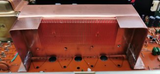
This looks really very neat! I can see that you take great pride in your work, well done. Definitely going to steal some ideas 😉So I've finally finished making the heatsink
Buy the way, what happened to the MM/MC connection?
I just havent put it back yet@poundy I have been following your thread for a while, and I'm learning a great deal from it, thank you for sharing!
I have a 3020 that's been in the family since new, about 1982/3
I recently bought a 3020A for 300ZAR (±£13) no cover, no base and very dirty. I am in the process of getting it back to a working condition and upgrade, hence the interest in your post. At this point I am stuck, needing an RCA MJ2955
Anyway, do you want to share the list of caps that you replaced? Will really help me if I get this one sorted.
Regards,
John
ok so that is a realy late one, just before the 'b' version and will have the board represented in these 2 diagramsI am really keen to take the RCA's off you if you want to sell them. I have family in the UK and my brother-in-law will be visiting there next week for 3 weeks. Maybe we can make a plan? The serial No. is B3224084
Your phono and power amp set up will be as diagram 1(3120)-your tone sections as per the next diagrams
Ive never been able to find an 'A' version manual so ive had to work it out working on various versions
The series 20 original had 2 setups basicaly, the late ones having the 'A' board but without the MM/MC circuit
The 'A's a combination of below and the B's a slightly different set up and power supply
Ive just checked my transistors and i only have NPN's no PNP'S sorry
you best bet is to buy these, ive used these and they are from a good supplier-if you buy a pair they will be batch matched
https://www.cricklewoodelectronics.com/2N3055H.html
https://www.cricklewoodelectronics.com/MJ2955.html
dont be tempted to get from ebay
good luck with your work👍
Last edited by a moderator:
I only buy specific makes, nichicon, Panasonic wurth cornell dublier best places are
CPC
RS components
Farnell
Digikey
Cricklewood will have caps that are OK, but unbranded
CPC
RS components
Farnell
Digikey
Cricklewood will have caps that are OK, but unbranded
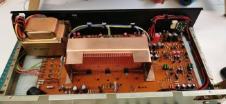
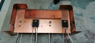
So the heatsink is finished and I've changed the right hand foot to encorporate the grounding connection. I made 2 small plates to screw through to from the foot plate. Now I'm about ready to start modding the transistors
I will trim the screws etc once I'm 100% happy I haven't got to alter anything.its taken alot to get to this point, but rather satisfying to see the end result so far
I will trim the screws etc once I'm 100% happy I haven't got to alter anything.its taken alot to get to this point, but rather satisfying to see the end result so far
Attachments
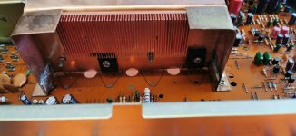

Yep they do that's why I've altered the pins so they are away a bit from them 😉The problem is that the caps are next to the regulators (trannies) , and the heat from them dries out the caps. 😉
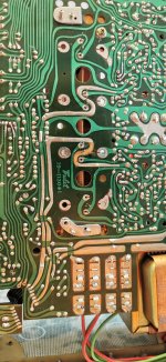
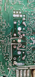
so ive come away from dropping them straight through each hole and swapping them over on the board.I didnt want to destroy it, but leave it in a way it could be put back as it was.
so the gate stopper is connected directly to the FET Gate and then i have a wire on each of the source and drains.This means i can cross them above and solder 3 at least direct to the original connections on the print
so the gate stopper is connected directly to the FET Gate and then i have a wire on each of the source and drains.This means i can cross them above and solder 3 at least direct to the original connections on the print
Attachments
- Home
- Amplifiers
- Solid State
- Last, but (hopefully) best ever modified and complete NAD 3020