So we have done a few of these over the last few years, but im hoping this could be the best one.
I will continue to repair these and other amps because i enjoy doing that side of it, but i want to start concentrating on learning more, and eventualy,if i ever get there, build my own from scratch.
But for now im taking a good condition 3020A(i made the mistake last time of converting one with faults, so this has been servied first) and going to convert it all to gold plated, change the rear terminals to gold plug ins, total recap, remove the driver stages and convert it to Lateral FETS.
I did convert some amps some time ago, but it was either with gold, but BJT's, or with TIP 35'S etc, but never all in one
so this one will be all of that but in one package.
I know NADS are like marmite, you either do or dont like them, so i guess this is for those who do.
STEP 1
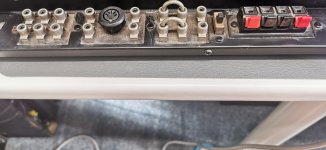
so to start with the rear has to be converted
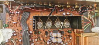
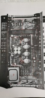
so the inside has had a first clean, it will get another later
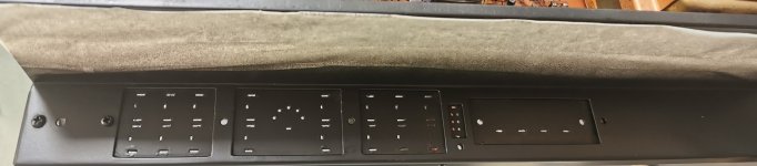
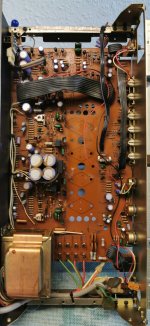
the rear has been stripped, cleaned and resprayed
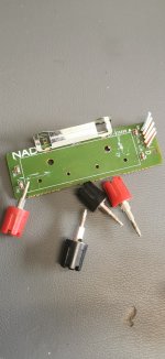
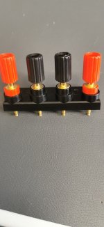
I have taken an old terminal assembly ,stripped it down and converted it to gold plug in terminals
STEP 2 will be to strip out the old transistors and get to work on what heatsink will be used and start the board conversion for the FETS
STEP 3 will be a second clean and recap
STEP 4 will be to do a dry run with the FET fitting
STEP 5 fit the FETS
STEP 6 mod the circuit
STEP 7 fit all the rear terminals
STEP 8 Testing
STEP 9 If all working ok, long soak testing
STEP 10 respray the main cover and assemble
I will continue to repair these and other amps because i enjoy doing that side of it, but i want to start concentrating on learning more, and eventualy,if i ever get there, build my own from scratch.
But for now im taking a good condition 3020A(i made the mistake last time of converting one with faults, so this has been servied first) and going to convert it all to gold plated, change the rear terminals to gold plug ins, total recap, remove the driver stages and convert it to Lateral FETS.
I did convert some amps some time ago, but it was either with gold, but BJT's, or with TIP 35'S etc, but never all in one
so this one will be all of that but in one package.
I know NADS are like marmite, you either do or dont like them, so i guess this is for those who do.
STEP 1
so to start with the rear has to be converted
so the inside has had a first clean, it will get another later
the rear has been stripped, cleaned and resprayed
I have taken an old terminal assembly ,stripped it down and converted it to gold plug in terminals
STEP 2 will be to strip out the old transistors and get to work on what heatsink will be used and start the board conversion for the FETS
STEP 3 will be a second clean and recap
STEP 4 will be to do a dry run with the FET fitting
STEP 5 fit the FETS
STEP 6 mod the circuit
STEP 7 fit all the rear terminals
STEP 8 Testing
STEP 9 If all working ok, long soak testing
STEP 10 respray the main cover and assemble
Attachments
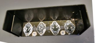
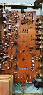
So the transistors have been stripped out with the heat sink. Excess solder removed from the terminal pads so I can see any cracks and the board cleaned again. Tomorrow I shall look at the heats ink and how I can adapt that or Introduce a complete new one, I'm also going to strip all the wiring out
Attachments
It's pretty good. This A version has the series 20 upgraded board where the regulated supply is incorporated onto the main board. The only difference is the introduction of the MM/MC phono circuit. Other than that they are identical, but much better quality than the original series 20.
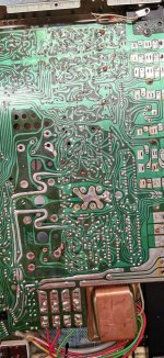
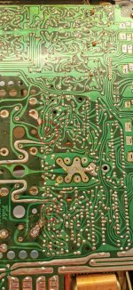
Just several reels of pressure-sensitive black crepe tape, lightbox and a scalpel... How it used to be done for years.Looking at that board, I wonder what experience and skill it takes to design such a meandering PCB.
I have a NAD C 320BEE which also has a meandering PCB. They must have software to design the layout. If not they would need to divide it into modules such as power supply, preamp, and power amp. It would be easier to repair but cost more.Looking at that board, I wonder what experience and skill it takes to design such a meandering PCB.
I wonder if there is software capable of converting a circuit schematic into a perfect PCB without human intervention to correct or adjust anything. For me, designing a board (not engraving one), the correct path for tracks, the correct placement of components is like a black art that is completely out of my mind.
I wonder if there is software capable of converting a circuit schematic into a perfect PCB without human intervention to correct or adjust anything. For me, designing a board (not engraving one), the correct path for tracks, the correct placement of components is like a black art that is completely out of my mind.
Engineers designing for a HiFi producer has to compromise with bean counters and marketeers. Often there are hard to repair monolithic PCBs just to save a few dollars. But you are the master of a DIY design and can make practical choices such as modular design. Software such as KiCad is good for layout but of course you must choose the best tracks.
Last edited by a moderator:
i think the answer to this question, or at least in this instance is that the practical outlay came first, the country lane effect as a result of that.I found this in one of the original manuals and it clearly shows each section numbered, well at least that would be my therory.I wonder if there is software capable of converting a circuit schematic into a perfect PCB without human intervention to correct or adjust anything. For me, designing a board (not engraving one), the correct path for tracks, the correct placement of components is like a black art that is completely out of my mind.
It might also explain why some other amps have a diabolical design, in that the printed side took preference
Attachments
Cool project, I've just re-engineered a vintage amplifier too!
I always thought these NADs had small main capacitors, it was the same in the original Cyrus One, that I also owned for a while. They reviewed well as they advertising spend was good, but fairly lightweight power in my experience, blown away by the grip and authority of my old DIY Maplin MOSFET amps (with split PSUs of 30,000uF per rail, per channel).
And so my thoughts, if that's ok, on this project - i.e. a suggestion of what I'd be doing .
.
1. Strip the PCB of all power amp components (including those lovely, original (genuine!!) TO3s, so it's just a pre-amp with some nice space.
2. Replace the mains transformer with a much smaller one, re-cap withe quality caps, bypassing all electros. This gives you a quality pre-amp.
3. Make as much space as possible - perhaps cutting the PCB or allowing space for mounting stalks and a horizontal metal screen...
4. Addition of two souped up Maplin Lateral MOSFET modules (PCBs available from James, here: https://www.diyaudio.com/community/...ga28f-construction-thread.257488/post-7646682 ).
(I actually have two spare heatsink brackets LOL, if you are near Cambridge)
5. Squash 2 100-150VA toroids in so the top half becomes a slim, 50Wpc+ power section
Maybe it's a bit extreme, but it would then be like those sleeper cars - looking ordinary but with some quality bite below the hood
I always thought these NADs had small main capacitors, it was the same in the original Cyrus One, that I also owned for a while. They reviewed well as they advertising spend was good, but fairly lightweight power in my experience, blown away by the grip and authority of my old DIY Maplin MOSFET amps (with split PSUs of 30,000uF per rail, per channel).
And so my thoughts, if that's ok, on this project - i.e. a suggestion of what I'd be doing
.1. Strip the PCB of all power amp components (including those lovely, original (genuine!!) TO3s, so it's just a pre-amp with some nice space.
2. Replace the mains transformer with a much smaller one, re-cap withe quality caps, bypassing all electros. This gives you a quality pre-amp.
3. Make as much space as possible - perhaps cutting the PCB or allowing space for mounting stalks and a horizontal metal screen...
4. Addition of two souped up Maplin Lateral MOSFET modules (PCBs available from James, here: https://www.diyaudio.com/community/...ga28f-construction-thread.257488/post-7646682 ).
(I actually have two spare heatsink brackets LOL, if you are near Cambridge)
5. Squash 2 100-150VA toroids in so the top half becomes a slim, 50Wpc+ power section
Maybe it's a bit extreme, but it would then be like those sleeper cars - looking ordinary but with some quality bite below the hood
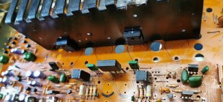
so continuing on then with STEP 2
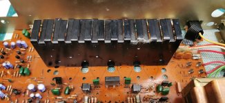
All of the wiring has been stripped out and i now have a clearer view of the areas.
I want to try and get a heatsink in where i can mount the FETS verticaly rather than just use the old heatsink and lay them down as i have before
The 2 multiplier positions need some work as the print came off when i moved them off the heatsink, but that should be too much of an issue, i will create some wire anchors.
So this will be the basic concept for the heatsink,but i will have to add some surface area behind as i dont think this on its own will be enough
Attachments
Last edited:
sounds like a great plan, maybe one for the future.Cool project, I've just re-engineered a vintage amplifier too!
I always thought these NADs had small main capacitors, it was the same in the original Cyrus One, that I also owned for a while. They reviewed well as they advertising spend was good, but fairly lightweight power in my experience, blown away by the grip and authority of my old DIY Maplin MOSFET amps (with split PSUs of 30,000uF per rail, per channel).
And so my thoughts, if that's ok, on this project - i.e. a suggestion of what I'd be doing
1. Strip the PCB of all power amp components (including those lovely, original (genuine!!) TO3s, so it's just a pre-amp with some nice space.
2. Replace the mains transformer with a much smaller one, re-cap withe quality caps, bypassing all electros. This gives you a quality pre-amp.
3. Make as much space as possible - perhaps cutting the PCB or allowing space for mounting stalks and a horizontal metal screen...
4. Addition of two souped up Maplin Lateral MOSFET modules (PCBs available from James, here: https://www.diyaudio.com/community/...ga28f-construction-thread.257488/post-7646682 ).
(I actually have two spare heatsink brackets LOL, if you are near Cambridge)
5. Squash 2 100-150VA toroids in so the top half becomes a slim, 50Wpc+ power section
Maybe it's a bit extreme, but it would then be like those sleeper cars - looking ordinary but with some quality bite below the hood
with this one i want to improve what i consider to be a good sound, but keep some of the originality, but i appreciate the input
- Home
- Amplifiers
- Solid State
- Last, but (hopefully) best ever modified and complete NAD 3020