4Hz would of course have the same level of IM products, but they'd be even closer (than mains AC) to associated frequencies, making them even harder for humans to hear. Kind of a lot of trouble to go through though, with the thermal inefficiencies of DC heating but without the CCS slow startup and isolation advantages of a proper Coleman type regulator.
In the old days of vacuum valve analog TV broadcasting, the output valve was a monster linear amplifier with DC heating (for noise reasons) that had automatic polarity switching at startup. They didn't usually get shut down and restarted much, but the cost of an output valve re-build (yes, they did that) was so high that this marginal advantage was taken. Different world from audio amps of course.
All good fortune,
Chris
ps; on/off/on switch will need to be 2 pole to switch polarity
Yes ive seen pictures of vuluptious woman sitting attop those water cooled monster emiac tubes. Also thats what i need an automatic polarity changer so my brain can relax and enjoy the dht music. Cheers.
You beat me to that idea, which isnt so stupid. The cathode / heater assemblies have a thermal time constant. Some of the big fat ones seem to still glow for, maybe 100s of ms after the power is switched off. Those thin little ribbon wire directly heated jobs cool down much faster, so depends on the tube.This might be a totally stupid question... But what if the oscillator were running at 4Hz instead of 100 kHz?
You want it slow enough to not be audible, but not so slow that you end up with an emissions based "tremolo" effect. I'm sure the frequency appropriate for a 6550 would be much different than for a 12AX7. With an efficient class D amp driving power, now you'd have 100kHz in there plus the problem of working out a frequency suitable for all the tubes comprising the amp. Unless you had separate drivers for each tube type...
Might give the amp a nice twinkle there in the dark. Course you could do that with LEDs embedded in the sockets ;')
Indeed, to phrase it in a more rigorous way: temperature is an INTENSIVE parameter in thermodynamics. That means that it is the same everywhere in the body (filament) in STATIONARY conditions (which is the case of heating the filament/heater of a tube with DC or periodic AC) and so, being the emission regulated by temperature, there is no variation of emission due to voltage gradient. There is a just a cloud of undistinguishable electrons around the cathode/filament.The filament rate of emission depends on the temperature of the filament material, and this temperature is a function of the current and resistance which don’t change along the length of filament with constant cross-section. There isn’t going to be any variation of emission along the filament due to the voltage gradient.

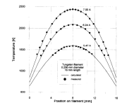
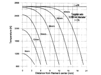
Just a to be precise, when I am saying temperature is the same everywhere, I mean and ideal case and that it does not change due to the voltage gradient. The applied voltage only impacts on the current flowing into the wire. Rather, the temperature will depend on the geometry/size/material. For the simple case of a single straight filament with DC supply from end-to-end, temperature is max at the center and lower at both ends! Symmetrical distribution, nothing like the voltage gradient. See picture on the left where it's case of a rather short wire. The longer the filament the more uniform and sharp temp becomes along the wire (picture on the left). It is the same everywhere for the "infinite" case.
Attachments
Might get end results similar to what the Tremolo circuit often found in guitar amps does.4Hz would of course have the same level of IM products
Looking at the pictures of EML tubes they seem to have multiple wires in parallel rather than 1 or max 2 wires running "along" the plate and folded over 1 or more times like the typical W-shaped filament or a single very long filament folded over many times and inserted into the cathode for indirectly heated tubes (to get them as practically long as possible). Still, given the large size of EML tubes those wires are surely much longer than the 16 mm wire showing temperature gradient and in the case of smaller plate tubes, like the EML30 or 20, only a fraction of the wires (the central part, where temp is uniform) goes into the plate.....
I am not sure the center-tapped ones are a good idea....it depends on where this tap is.
I am not sure the center-tapped ones are a good idea....it depends on where this tap is.
Attachments

Why stop at 4 Hz? Why not 0.4 Hz? Maybe use a handful of MOSFETs to swap the polarity of a DC source. 🙂 
Tom
Tom
The filament rate of emission depends on the temperature of the filament material, and this temperature is a function of the current and resistance which don’t change along the length of filament with constant cross-section. There isn’t going to be any variation of emission along the filament due to the voltage gradient. In practice, there will be variations in the filament temperature due to different rates of heat loss from the filament along it's length, e.g.- the ends will be in contact with colder supports. For the purposes of this thread though, the emission can be said to be uniform and constant along the filament. Think of the case of a series string of identical power resistors, this will all have the same power dissipation, and in the same environment the will all reach the same temperature despite having a voltage gradient along the string.
Where the voltage gradient has an impact on the tube is to create a gradient in the filament-grid bias because the grid is at an equipotential (it should have a negligible voltage gradient of it's own) . This bias directly controls the cathode-plate current and the dc voltage gradient along the filament will result in a variation in the current flow between the filament and the plate depending on the geometry of filament-plate. This would happen with AC heating too of .
That could work, but in the case of a tube like 300B with a direct heated filament having a low thermal mass, its temperature could fluctuate with a polarity reversal speed as low as 4Hz. The effect could well be audible. I would think that if you use a reversal frequency that's just above the audible frequency range, then it could work. An excessively high switching frequency could introduce HF hash into the audio signal.This might be a totally stupid question... But what if the oscillator were running at 4Hz instead of 100 kHz? It would change polarity 4 times a second but still be AC outside of human hearing range. Be kind, I'm a beginner just throwing that out there since the polarity discussion.
More stupid Newby questions...
Well a low frequency AC supply would eliminate the concerns some have over long term DC polarity mentioned, because polarity is changing. You wouldn't need a wide band class D amplifier either, another benefit. Now let's ask, if the class D amplifier heating method is used at a subsonic frequency... I assume that would be like/analogous to an AC voltage regulated supply right? IOW it should hold a constant voltage once the volume control is set to the desired voltage. Now a voltage regulated supply, AC or DC will have a lot of inrush unless it has a slow start transistor right? So to address inrush, another cause of tube life shortening...
How do we do the same low freq AC supply but as a current regulated supply? Because current regulated supplies inherently don't suffer the tube to inrush, right? Can a off the shelf class D amplifier heat a tube as a constant current supply? Easy modifications to do this? A slow start circuit, if not CC, would suffice too.
Last edited:
I think that's quite clever. IMD will be the same as 50Hz but at -40dB down you won't hear it. I'll stick with DC.
I remember fixing a guitar bass amp for somebody. Bought on ebay plugged it in - set for 120V and got 230V. It had a mains switcher using a little 8-pin chip some rather overrated MOSFETS and operated as a transformer at 100KHz. Cannot remember the chip IR2153 something. Was unregulated, but you could power a number of 300B with a rewound transformer. All the semiconductors and electrolytics were replaced and it was up a running again. However it was a square wave output and would need flitering.
Last edited:
That could work, but in the case of a tube like 300B with a direct heated filament having a low thermal mass, its temperature could fluctuate with a polarity reversal speed as low as 4Hz. The effect could well be audible. I would think that if you use a reversal frequency that's just above the audible frequency range, then it could work. An excessively high switching frequency could introduce HF hash into the audio signal.
My 69 year old ears cut off at 9kHz these days 11kHz on a good day. I've found there isn't really much musically above 10kHz that I miss. 🙄
Member
Joined 2009
Paid Member
On another forum (can't remember at this moment) there were threads about using 'dc transformers' aimed at 12V halogen lights which they opened up and changed the number of turns on the output transformer to match the filament voltage. These are usually working at just above the audio range and most of the fellas also modified the unit to push the frequency up a bit more. They produce some ugly waveforms but those who tried them said there were no issues with the sound at all. I bought a couple of these cheapo units to try out but they are waiting in the project queue......
It might have been audiokarma but I don't look there anymore, they're drowning in ads.
Edit: we have a home-grown thread here: https://www.diyaudio.com/community/threads/new-idea-of-dht-heater-supply.51599/
It might have been audiokarma but I don't look there anymore, they're drowning in ads.
Edit: we have a home-grown thread here: https://www.diyaudio.com/community/threads/new-idea-of-dht-heater-supply.51599/
I think that using a frequency of hundreds of Khz to heat the filament can raise some problems, such as the film effect, i.e. the circulation of current at the surface of the conductor (filament), or I don't think this aspect has been studied
It seems nobody bothered to read the solution mentionned in post #5 at the very beginning of this thread. I have gone this route and it is much simpler than the convoluted contraptions I see around. I have built a few, both for me and for a friend, and they are dead silent at all power levels, be it in DH or IDH filaments. Silver-plated wire secondaries for DH filaments please 😎


I used a simple input capacitor to reduce ripple but in my next project I'll be regulating the HV upstream of the "electronic transformer", allowing super stable filament voltage and no need to rewire the transformer secondary by adjusting the input voltage at the regulator.
I used a simple input capacitor to reduce ripple but in my next project I'll be regulating the HV upstream of the "electronic transformer", allowing super stable filament voltage and no need to rewire the transformer secondary by adjusting the input voltage at the regulator.
Last edited:
As I attempted to say, depends on the thermal time constant of the cathode heater structure. The control circuit could be like a thermostat; measure the heater temperature via resistance between the power pulses, or polarity swaps.Why stop at 4 Hz? Why not 0.4 Hz?
Why should one bother after reading nonsense like this (in the first link)?It seems nobody bothered to read the solution mentionned in post #5 at the very beginning of this thread.
"One obvious solution is DC heating, which should be hum free. I personally dislike the effect DC heating has on the sound, a specific type of detail muffling and bass tone exaggeration, and am aware of the other problems inherent with DC heating, like the difference in heater potential from one end of the heater to the other, or the need to switch current direction (polarity) at least from time to time in order to keep the filaments in best operating condition."
Last edited:
- Home
- Amplifiers
- Tubes / Valves
- Using an audio amplifier to heat filaments (high freq. AC)?