It's easy just with RF to balance heater supply with a pair of equal chokes instead of grounding the filamentary cathode at one side.Putting an Ampere-level HF signal into a DHT filament (one side of which is grounded, out of necessity) and then an AF signal into the grid is going to radiate carrier and AF sidebands, regardless of any matching.
Best regatrds!
Ferrite inductors are notably bad-sounding in speaker crossovers; I would not have them in an amplifier.
Each to their own tastes though...
Each to their own tastes though...
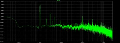
The plot posted by @euro21 shows no sign of cancellation in this case.Rod I think for PP amp with a CT sinewave drive on each tube you will just get 2nd harmonic both outputs in phase which will cancel at the OPT
So it's probably easier to just measure the proposed circuit and see.
I agree that square wave heating is much worse than sine wave for near-field coupling, and also for conducted emissions running back through the mains; a potential coupling into the DAC and its oscillator. (My DAC oscillator runs from two stages of regulation, including a high RF rejection stage, and a separate winding for the PT. I am certain that this is worthwhile, even without big noise generators nearby).
Yes by the time you get to 2x100KHz the OPT windings will no longer be in anti-phase, so you may well get reduced cancellation. The conducted emissions back through the mains needs the same treatment as any SMPS. The problems at the output side are much easier to deal with than a class D amp, where you have PWM many tens of volts into a LPF before the speaker.
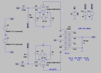
OK I assume the 300B composite is a number of tubes. If you swap the +/- of the bottom AC source you will get different results. What I would be doing is CT the heater source with the 1R on the CT.
Member
Joined 2009
Paid Member
How would one go about using a power tube in Class C as a power oscillator for generating the h.f. Heating supply ?
I’ve always thought it would be kinda neat to use a tube like this, some of which were designed to be used in Class C before audio folk adopted them. I assume a step down transformer will be needed for matching to the heater.
I’ve always thought it would be kinda neat to use a tube like this, some of which were designed to be used in Class C before audio folk adopted them. I assume a step down transformer will be needed for matching to the heater.
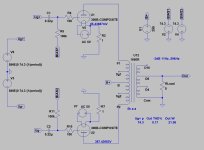
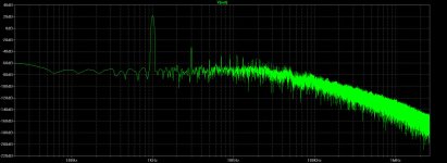
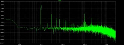
Ideal transformers don't exist. You have significant capacitance, leakage inductance and imbalance to deal withSome simulations:
300B PP with 100kHz sine and 100kHz SQ filament.
View attachment 1298846
View attachment 1298847 View attachment 1298848
Think I mentioned somewhere in this thread, an 807 is good for 40 watts continuously as a Class C oscillator or amplifier.How would one go about using a power tube in Class C as a power oscillator for generating the h.f. Heating suppl
Since the tube will be running at some yet undefined frequency, maybe 100 KHz, the windings on the hot inductors
need to formed in Litz wire, just as they are in induction heating stove tops. In the 50s when this was a topic of discussion
807s & 2A3s were almost being given away on the surplus market. There were boxes of them in the lab were I worked
beginning in 1957, gifts from the military, Etc.
So today some kind of power FET is a better choice. Unless we want something to look at.
Attachments
Michael C said:
Its a great idea.traditional dc heating upsets the heater emmison along the filiament.
The DC vs AC issue may may not apply too much to small directly heated tubes that can last for decades of continuous light-duty use, but on tubes with significant emission and moderate to high temperatures, there is the matter of the long term emission life of a DC-operated filament.Oh? How so?
As far as I understand it, the cathode/filament will emit electrons once it gets hot enough. These electrons from a space charge cloud around the cathode as they repel each other. As all electrons have the same charge, they will be evenly distributed in the space charge cloud and one electron will be indistinguishable from the other. Why would it matter whether the cathode is heated by LF AC, HF AC, or DC ... or by a heater?
Tom
When powered by DC, the emission current along the filament from the negative end to the positive end is not uniform due to the grid-to cathode bias gradient along the filament structure. That is, on an example DC-powered 7.5V filament, one end is at -3.75V compated to the center, and the othe end is at +3.75V. The more sensitive the tube is, the larger an emission current gradient along the filament will be. The more negative end will wear out first.
When a tube that is sensitive to this effect, such as when the filament base material can deterioirate and increase resistance or become embrittled and fail, and the tube cost hundreds of $ and up, or is hard to get, then it's best to run AC on the filament. The only choice is the frequency to be used.
When DC is not avoidable, the advice is to periodically reverse the DC polarity on the filament. I can not recall right now where I read this, but it was in a power tube manufacturer's book or data sheet.
To which tubes would this apply and how bad is it? I don't know that. I would never consider running anything with a thoriated tunsten filament on DC. The 3-500Zs and their ilk are safe here. Nor would I run a costly 211 or 838 that way. I have no experience with tubes like the 2A3 which operate at lower filament temperature, but the bias gradient still remains, and whether it's important on tubes like that I don't know.
It's not ideal. Simplificated, but near to the real.Ideal transformers don't exist. You have significant capacitance, leakage inductance and imbalance to deal with
.SUBCKT 1650R P1 Sg1 B Sg2 P2 O16 O8 O4 Com
- Push Pull transformer, with Ultralinear taps at 40%
- 5000 to 16 ohms, with 8 ohm and 4 ohm taps, 3db 15 to 60Khz
- Hammond 1650R
LP1 1 2 2.409088925H ; PRIMARY
LS1 2 B 1.070706189H ; primary, scrren grid tap portion
LS2 B 3 1.070706189H
LP2 3 4 2.409088925H
LA1 5 6 0.007348166H ; SPEAKER SECONDARY
LA2 6 7 0.003674083H
LA3 7 Com 0.021414124H
KALL LP1 LS1 LS2 LP2 LA1 LA2 LA3 0.999199994;
RP1 P1 1 30.0
RP2 Sg1 2 15.0
RP3 Sg2 3 15.0
RP4 P2 4 30.0
RS1 O16 5 0.1
RS2 O8 6 0.1
RS3 O4 7 0.1
.ENDS 1650R
If you have better model for Hammond 1650R, shows it.
Running Thoriated filaments on Mains Line AC is a sure recipe for shortening the life of the filament, not extending it!I would never consider running anything with a thoriated tunsten filament on DC. The 3-500Zs and their ilk are safe here. Nor would I run a costly 211 or 838 that way. I have no experience with tubes like the 2A3
Firstly, with home audio, we usually power ON and OFF every time we listen, unlike the radio stations that could leave them on constantly. With most AC setups, the startup current is under very little restriction, and so the stress at power-ON is much worse that a controlled startup possible with DC regulation. I know we can use NTCs, but that does no offer the same level of control.
Secondly, AC mains line voltages are unregulated, so the applied heating voltage follows the rise and fall of the line voltage. This can easily be 5 or even 10% (In the UK, the limit was actually degraded to ±10% a few years ago.
Running higher OR lower by only a few % of Vf(nominal) destroys the lifetime of the filament, as this Application Brief for EIMAC shows only too clearly:
It shows that without regulation, the filament voltage must be run at 100% of rated voltage, becuase Line dips do more damage than rises.
But regulation to 1% (preferably) up to 3% allows operation at 95% of nominal voltage, which more than doubles the lifetime of the filament compared to 100%.
The idea that skewing of the filament current from DC heating reduces filament life has been debunked - with evidence - in this thread. Please have a look, especially noting the temperature plots posted by member @45 .
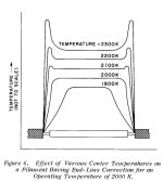
Overheating or underheating of TT filament may generate unevenness of temperature distribution via the wire.
The moderate temperature variation manageable, severe overheating may sooner or later will degrade the filament.
Underheating -if it is significant- not recommended for power tubes, the emitting surface may drastically decreases, the extractable power too.
Sample:
http://www.r-type.org/pdfs/thoria05.pdf
The moderate temperature variation manageable, severe overheating may sooner or later will degrade the filament.
Underheating -if it is significant- not recommended for power tubes, the emitting surface may drastically decreases, the extractable power too.
Sample:

http://www.r-type.org/pdfs/thoria05.pdf
In 45 datasheet posted all the typical configuration of amplifier are listed with ac filaments and not dc
I built some 300B p-p mainly in the year 1998-2010 and are still running fine with ac filaments and the regulation of bias is checked around one time year and in some cases nothing to move
( quality of tube of course)
Then everyone can use the way where is confident


Walter
I built some 300B p-p mainly in the year 1998-2010 and are still running fine with ac filaments and the regulation of bias is checked around one time year and in some cases nothing to move
( quality of tube of course)
Then everyone can use the way where is confident
Walter
RCA data sheet for 45 indicates AC or DC. But tht does not mean anything about the lifetime - especially with today's tolerances. ±10% on AC mains will give short life if it gets that bad during use.

I'm liking sub-human frequencies over super-human, as I think about it. The question is how long does a filament take to cool when it goes to zero volts. With AC the tube will always be getting twice as many full voltage pulses as zero volt valleys. At .4 Hz the zero or near zero voltage time is too long, the filament has time to cool. At 4Hz its getting 8 full voltage swings and 4 zero crossings, still too much time to cool, I gut feel. At 8Hz 16 full voltage 8 zero crossings per second, better, but we still have room to go faster. 16Hz might be ideal, with 32 full voltage swings per second, I don't think it will have any chance to cool and we're below the theoretical 20Hz. I don't believe anyone actually can hear 20Hz, you only feel it. In my youth 30Hz was just barely "actually heard" even. I'm thinking 16 Hz to be a good compromise between DC and 60Hz.if one already wanted an AC option. I could see an Amp with a switch on the back for DC or 16Hz AC option. Slow starting a filament is also a good thing, the class D amp would need a way to ramp up its volume control. DC current regulated is inherently slow start. Voltage regulated DC could use the transistor and RC time method described in the LM317 pdf.
Last edited:
- Home
- Amplifiers
- Tubes / Valves
- Using an audio amplifier to heat filaments (high freq. AC)?
