
Your cap values indicate a crossoverpoint at 1k according to MR's app: (http://doublesecretlabs.com/apps/passxo/)I'm trying to put together a DigiKey order and am a bit stumped on the C & C/2 caps. My target crossover point is 650 hz and I have calculated C = 9.231 (10) nF = .010 mF = 10,000 pF and C/2 = 4.615 nF = .0047 mF = 4,700 pF.
bw attila
@Attila I
I'm not clear how to use MR's app. I based my calculations on the original Nelson Pass paper where he suggested the following calculations:
For 6 & 12 dB/octave slopes, C= 6000/frequency (e.g. 6000/650 = 9.231 nF)
For 18 & 24 dB/octave slopes, C= 7000/frequency (e.g. 7000/650 = 10.769 nF)
If I'm reading the default app values correctly, the resistor values shown don't seem to match anything on the original parts list. Is there something you can point me to that will help me understand this better?
I apologize for my ignorance, but I have no idea what items on the parts list or on the PCB correspond to the values of R 1-8 and C 1-8. Even more so, what P1 & 2 relate to. I assume they are pots and possibly correspond to one or more of the R selections, but I'm really at a loss. Also, in the example you've shown of your results, yours displays schematics for high and low. When I access the app, I do not see that.
I'm trying to learn and appreciate all the help I can get. I just don't have the background to know these things.
I'm trying to learn and appreciate all the help I can get. I just don't have the background to know these things.
R1-8 correspond to the trimmer pots(P1 & P2) in series with the 10k resistors. So 10K + 50k(when the trimpot is fully counter clockwise). C1-8 correspond to the C values in the article except for C6 & C8. Which are C/2.
I had never used that app before so I was confused by the discrepancy between the formulas in Nelson's article and Attila's findings. Playing with the app a little I see that the formulas in Nelson's article expect the trimpots to be at full resistance(and half). With the P1 trimpots fully counter clockwise and P2 trimpots at halfway, the cap values you previously chosen(10nF & 4.7nF) will sum flat at 650hz.
These are just the transfer functions of the filter though. With real speaker drivers, adjustment is needed. Do you have a measurement mic?
@CWelsh52
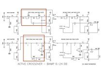
look at the schematic - see the filter cells (red) - in the low pass there are resistors (10k + P1 and 10k + P2) in series and capacitors c & c/2 aside.
same as R5, R6, C5, C6 in the app.
No idea why you can't see the whole app (scroll down or up?)
cheers
Attila
look at the schematic - see the filter cells (red) - in the low pass there are resistors (10k + P1 and 10k + P2) in series and capacitors c & c/2 aside.
same as R5, R6, C5, C6 in the app.
No idea why you can't see the whole app (scroll down or up?)
cheers
Attila
Attachments
Thank you, @thirdicomplex ! This really helps.
I do not have a measurement mic at this point, but will buy one. Any suggestions? I use a Mac if that makes any difference. I also believe there have been suggestions for measurement apps elsewhere in this thread.
I do not have a measurement mic at this point, but will buy one. Any suggestions? I use a Mac if that makes any difference. I also believe there have been suggestions for measurement apps elsewhere in this thread.
Should have just jumped right in instead of pouring that second cup of coffee...LOLtoo late again...
I'm happy to receive help and information whenever. I don't know why I can't see the full app, either. There is a note on the bottom about "opening"...oh, wait...I just went back to the link and reopened the app and the schematics are there. I was just at the doctor yesterday for my annual Medicare wellness check. I don't think I want to tell her about this, but I know what happened. If you switch from the 18/24 selection to 6/12, the schematics go away. Switching back does not restore them. You have to leave the app and relaunch it to get them back.
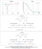
I've been playing with the XO app and have come up with the following. The summed value isn't perfectly flat, but darned close. The high and low values are down 4.5 dB at the crossover. Do I need to be concerned about the Phase traces, though?
I've played with some other settings that pull all of the Phase traces together, but then the crossover point drops to about 550 instead of 650 hz.

I've played with some other settings that pull all of the Phase traces together, but then the crossover point drops to about 550 instead of 650 hz.
@Davey and anyone interested, following the previous lumpy in room measurements of my daisy chain 4 way system with three DIY biamp boards at 120Hz, 1kHz and 7kHz posted at; https://www.diyaudio.com/community/threads/diy-biamp-6-24-crossover.357657/post-7597572
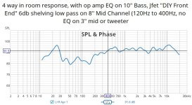
I have now added a 120Hz to 400Hz 6dB Shelving Low Pass (SLP) EQ section to the 8" channel, using a pair of DIY Front End Jfet boards to the ASP to try to improve the mid bass open baffle frequency response. The non-inverting SLP lower gain is x3.3 (@120Hz) and upper gain is x1.0 (@400Hz) connected between the o/p of the DIY BIAMP 120Hz-1000Hz band pass channel and this channels amplifier input.
I've attached the measured overall in room response below which shows a more well behaved curve (compared to the previous response) and I'm able to play around with the relative levels on each channel to get a better listening balance. I prefer to reduce a bit the lower channel below 120Hz as my garage listening room is not very well behaved in this region. The SLP addition gives better mid bass crossover between 10" woofer and 8" mid bass while noticeably improving the perceived overall tonality (slightly warmer). I haven't yet done outside measurements and individual measurements of the 8" channel with SLP EQ which is next up when the weather allows.
I'm thinking of a future experiment to change the 3" seas for a 5" driver so I could rearrange crossover points to approx say; 90Hz, 400Hz & 3kHz in order to play around with Thorsten Loeschs' tips on Blauert band EQ target curves from a good few years back.
Any suggestions and comments welcome.
Attachments
Last edited:
Hi Attila -you have to adjust P1 & P2 (0-50k) to your calculations (including the 10k resistors)
just play with the app until you get the slopes right (thats what i did)
e.g. my slob results
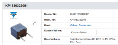
I like your values here. Question: Where did you source 24nf and 23nf film capacitors?
Thanks very much,
Jim
@Attila I @thirdicomplex @cubicincher
Thank you all for your guidance and indulging my questions. I've figured out my parts order. Now all I have to do is pull the trigger then get to building. However...
I've discovered a problem with hanging around and surfing through these forums. Too many ideas! Too many options! Too many possibilities! LOL I now have a list of future projects that I want to put ahead of the biamp crossover. A tube preamp then another ACA for example. And, someday, there is going to be that SET amp. Falling further and further down the hole.
Hey Jim,Hi Attila -
I like your values here. Question: Where did you source 24nf and 23nf film capacitors?
Thanks very much,
Jim
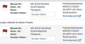
I used the Roederstein type, but there are also the slightly bigger types from Panasonic though you would have to bend the leads.
Attachments
Pleased to report Attila's values from post #1504 above worked for me. Running Altec 420a high/mid, on top of the speaker camp SLOB bottom Eminence Beta 15. SissySit above ~100Hz, M2X below. I was careful to set the pots w/ DMM per the simulator. Having an early listen it's certainly no worse than the stock speaker camp MiniLx active analog crossover.
My understanding of these is now only slightly less miniscule
My understanding of these is now only slightly less miniscule
My understanding of these is now only slightly less miniscule
No kidding! Makes me very humble.
- Home
- Amplifiers
- Pass Labs
- DIY biamp 6-24 crossover