
Intriguing. Good to know.just connected audio interface input gnd with usb gnd
Tom
Yeah what’s noteworthy is that Modulus 86 has amazing PSRR. There is no 60hz ripple on the graph at all - buried below the noise floor. And that is with smps.
My other amp with linear psu 44,000uF per rail and plain lm3886 has ripple at -120db and still visible on the measurements.
My other amp with linear psu 44,000uF per rail and plain lm3886 has ripple at -120db and still visible on the measurements.
By the way, is it worth it to replace all capacitors in the audio path to film type? just curious…
I know Tom did some testing and measured the distortions of nichicon ES caps. It would be kind of difficult to replace 100uf bipolar caps with film caps, space and cost.
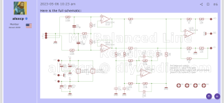
But take a look at “My Balanced Line Receiver” designed by Alexcp https://www.diyaudio.com/community/threads/my-balanced-line-receiver.398440/
He is not using capacitors.
But take a look at “My Balanced Line Receiver” designed by Alexcp https://www.diyaudio.com/community/threads/my-balanced-line-receiver.398440/
He is not using capacitors.
Attachments
I know Tom did some testing and measured the distortions of nichicon ES caps. It would be kind of difficult to replace 100uf bipolar caps with film caps, space and cost.
But take a look at “My Balanced Line Receiver” designed by Alexcp https://www.diyaudio.com/community/threads/my-balanced-line-receiver.398440/
He is not using capacitors.
Reminds me of Bruno Putzeys the g word article example towards the end of the article
NP0/C0G is better than film, actually. Audiophiles will disagree, but in reality that ceramic is a better dielectric than polypropylene film. This was confirmed by Bruce Hofer (AP) some 10ish years ago.I was thinking about NP0 type like 33pf etc
You could consider replacing some of the X7R/X5R capacitors with film types. None of them act within the audio band, though, so you won't hear any difference. But maybe it'll feel more audiophile or something. 🙂 There used to be a film cap in the Zobel network, but I replaced it with X7R because I was already using 100 nF X7R for the decoupling capacitors, so I could save you a few bucks due to the bulk discount. I have not been able to measure or hear any difference.
One could maybe make a technical argument for replacing R2 with a type that has even lower temperature and voltage coefficient. I doubt it'll make any difference as R2 is inside the error correction loop, but that spot would be a prime target for experimentation. R7 and R18 too, but they're already ±0.1% types with low tempco.
Tom
NP0/C0G is a stability category, not a specific dielectric, so there will be some variation, but no gross misbehaviour like the ferro-electric dielectrics in other ceramic caps.
Random C0G caps bought from eBay may or may not be C0G, note.
Random C0G caps bought from eBay may or may not be C0G, note.
Fair enough.NP0/C0G is a stability category, not a specific dielectric
And you're 200 % right regarding components on ePay/AliBlahBlah/Bezos' et al.
Tom
NP0/C0G is better than film, actually. Audiophiles will disagree, but in reality that ceramic is a better dielectric than polypropylene film. This was confirmed by Bruce Hofer (AP) some 10ish years ago.
You could consider replacing some of the X7R/X5R capacitors with film types. None of them act within the audio band, though, so you won't hear any difference. But maybe it'll feel more audiophile or something. 🙂 There used to be a film cap in the Zobel network, but I replaced it with X7R because I was already using 100 nF X7R for the decoupling capacitors, so I could save you a few bucks due to the bulk discount. I have not been able to measure or hear any difference.
One could maybe make a technical argument for replacing R2 with a type that has even lower temperature and voltage coefficient. I doubt it'll make any difference as R2 is inside the error correction loop, but that spot would be a prime target for experimentation. R7 and R18 too, but they're already ±0.1% types with low tempco.
Tom
When I was selecting bypass capacitors for my other LM3886 build I noticed that there is a vendor tool for SMD caps that shows capacitor’s performance depending on various factors such as physical size, DC voltage applied, or DC voltage rating, etc. I went with 2u2 1210 50v cap as it showed best capacitance vs DC voltage applied performance.
When I was desoldering through hole type TDK blue colored ceramic capacitors one time I accidentally broke it apart and I noticed that it was 0603 cap inside. It simply had leads soldered to it.
With all that in mind I wonder now if it is any beneficial to get say 1206 size SMD cap and use it in place of those through hole blue ones (on Modulus board)? Theoretically it should have better characteristics because of the bigger size?
Last edited:
The Murata SimSurfer tool is excellent for capacitor characteristics. I use Murata caps a lot as result.
Honestly, the 100 nF X5R/X7R capacitors are not critical. You can experiment if you want, but I doubt you'll get much out of that. That said, you should be able to solder a 1206 sized cap directly onto the footprint for the bypass capacitors. The pin spacing is 0.2" and the pads are 0.080" in diameter, so there's plenty of copper to attach to.
I have noticed that physically larger X5R/X7R capacitors tend to offer higher capacitance for the same DC bias. The difference between 1206 and 0603 isn't dramatic as I recall, but the physically smaller capacitors (0402 and below) tend to feature pretty horrid voltage coefficients. Even 1206 or 0603 won't offer much more than 15-20 % of the marked capacitance, if that, at the full rated voltage.
Tom
Honestly, the 100 nF X5R/X7R capacitors are not critical. You can experiment if you want, but I doubt you'll get much out of that. That said, you should be able to solder a 1206 sized cap directly onto the footprint for the bypass capacitors. The pin spacing is 0.2" and the pads are 0.080" in diameter, so there's plenty of copper to attach to.
That's too funny. I can't say I'm surprised, though.When I was desoldering through hole type TDK blue colored ceramic capacitors one time I accidentally broke it apart and I noticed that it was 0603 cap inside. It simply had leads soldered to it.
I have noticed that physically larger X5R/X7R capacitors tend to offer higher capacitance for the same DC bias. The difference between 1206 and 0603 isn't dramatic as I recall, but the physically smaller capacitors (0402 and below) tend to feature pretty horrid voltage coefficients. Even 1206 or 0603 won't offer much more than 15-20 % of the marked capacitance, if that, at the full rated voltage.
Tom
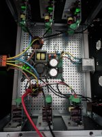
Coming back with some progress, things are mounted and wired. So I can test modules one by one.
Not sure I'm doing this correctly. I have no load on the output. And put 500mv sine wave to the input.
it's very noisy on the output with no input.
Should I be worries?
Not sure I'm doing this correctly. I have no load on the output. And put 500mv sine wave to the input.
it's very noisy on the output with no input.
Should I be worries?
Attachments
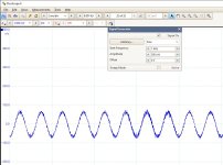
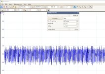
Your first scope pictures shows more like 50 mV sine wave. I'm not sure what to make of the second image. Is that the noise you're talking about?
You will get higher output noise with the input floating as the amp will then amplify the thermal noise of the 48 kΩ input impedance. That goes away when you plug a source in as the source output impedance (typ. < 100 Ω) will then be in parallel with the input impedance of the amp. That said, I'm not able to hear any noise in the speakers even with the input to the amp unplugged. I haven't measured in that specific condition, but I would expect the amp to have less than 100 uV RMS of output noise with the input floating. But with the input floating the input wiring has a good chance of acting as antenna, so you could be picking up all sorts of noise there that is then amplified.
If the noise goes away with the input to the amp shorted, I wouldn't worry about it.
Tom
You realize one of the features of SMPS is the lack of mains ripple?There is no 60hz ripple on the graph at all - buried below the noise floor. And that is with smps.
Well.... Depends. The SMPS starts with rectification of the incoming mains voltage. The rectifier can emit mains hum that can couple into sensitive circuits, such as amplifier inputs. I saw that with the Modulus-286 Kit LE.
That said, there tends to be little mains hum left on the output voltage of an SMPS. There's often a bunch of switching hash, but that can (often) be dealt with.
Tom
That said, there tends to be little mains hum left on the output voltage of an SMPS. There's often a bunch of switching hash, but that can (often) be dealt with.
Tom
SMPS's are a feedback system so they have lots of mains rejection. A transformer + rectifier + filter caps has poor mains rejection - that's the sort of PSU that really tests an amp's PSRR. A transformer is going to generate a lot more magnetic radiation than a single loop of traces in the SMPS rectifier circuit, I suggest...
Of course SMPS can produce lots of non-mains related frequencies, often the deal-breaker.
Of course SMPS can produce lots of non-mains related frequencies, often the deal-breaker.
Mark, we fundamentally agree. I'm just pointing out that some SMPSes (including the Connex SMPS300RE and SMPS300REh) will radiate mains hum from the rectifier. They still have lots of rejection from input to output.
The switching hash can be a dealbreaker, but it's often easy to filter out. Filter components aren't super cheap, but a lot lower cost for a 50 kHz filter than for a 50 Hz one.
Tom
The switching hash can be a dealbreaker, but it's often easy to filter out. Filter components aren't super cheap, but a lot lower cost for a 50 kHz filter than for a 50 Hz one.
Tom
I think you means mains buzz, rather than hum, from the rectifier - the harmonics of buzz go way higher and are less well rejected than hum.
- Home
- Amplifiers
- Chip Amps
- Modulus-86 build thread