Each one of the Mod Team is doing a great job!
And the Team as a whole is the complementary strength of the forum (the primary, is the forum's membership)
George
And the Team as a whole is the complementary strength of the forum (the primary, is the forum's membership)
George

Is REW a dependable tool? I have noticed it always shows better ENOB & THD than my software.
I’d rather believe in more modest specs.
I’d rather believe in more modest specs.
hi,ska:could you publish this dac's boomSo far, I haven’t made a decision yet. I spent a lot of personal time developing this project and I am almost of the age of retirement. It would be nice to have some small income out of it in the future.
I wrote a new experimental version of FPGA code for 24.576/22.5792M oscillators with 14tap FIRDAC.
I also studied and tweaked REW for correct compensation of the notch filter.
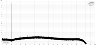
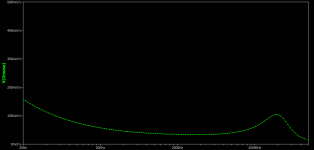
Here you can see the results for 1K & 10K 0dbFS.
I also studied and tweaked REW for correct compensation of the notch filter.
Here you can see the results for 1K & 10K 0dbFS.
Attachments
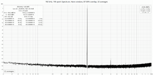
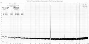
The results are impressive.🙂 Standard 1-bit DSMs don't exhibit such characteristics. I believe Chord may offer the best numbers, but THD and SNR would probably be around 115 dB. Only Molamola, which uses PWM, achieves such figures. PWM seems to be the differentiating factor.
One curious aspect is that the SNR is around 105 dB. I use a 2-bit DSM, where THD and SNR are essentially the same thing. One doesn't typically improve without the other. This was also the case with 1-bit DSM. This might be the advantage of PWM. When using a 2-bit DSM, both THD and SNR approach 120dB. While THD is slightly better in terms of numbers, the reproducibility is significantly higher compared to 1-bit DSM. When multiple boards are made using PWM, will they all have the same numbers?
One curious aspect is that the SNR is around 105 dB. I use a 2-bit DSM, where THD and SNR are essentially the same thing. One doesn't typically improve without the other. This was also the case with 1-bit DSM. This might be the advantage of PWM. When using a 2-bit DSM, both THD and SNR approach 120dB. While THD is slightly better in terms of numbers, the reproducibility is significantly higher compared to 1-bit DSM. When multiple boards are made using PWM, will they all have the same numbers?
PWM DAC has absolute differential linearity. That means, that just increasing noise filtering (or number of FFT points) you can see harmonics below noise level.The results are impressive.🙂 Standard 1-bit DSMs don't exhibit such characteristics. I believe Chord may offer the best numbers, but THD and SNR would probably be around 115 dB. Only Molamola, which uses PWM, achieves such figures. PWM seems to be the differentiating factor.
One curious aspect is that the SNR is around 105 dB. I use a 2-bit DSM, where THD and SNR are essentially the same thing. One doesn't typically improve without the other. This was also the case with 1-bit DSM. This might be the advantage of PWM. When using a 2-bit DSM, both THD and SNR approach 120dB. While THD is slightly better in terms of numbers, the reproducibility is significantly higher compared to 1-bit DSM. When multiple boards are made using PWM, will they all have the same numbers?
So THD can be a lot better than THD+N.
The 3-rd harmonic was caused by nonlinearity of the CMOS outputs. It could be reduced further by loading FIRDAC with very low impedance LPF.
The SNR 105dB is defined by dominant noise of analog LPF, because the noise floor precisely follows PSPICE noise simulation.
You can see it on 10k plot, it has a bump ~40k as predicted by SPICE.
The benefit of PWM modulation is very low switching frequency of 1-bit output. And PWM spurs can be easily eliminated by simple moving average (FIRDAC).
By now I assembled 2 slightly different versions of the boards, they both have the same performance. The design is reproducible.
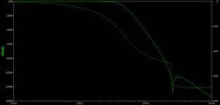
TNT: I used very simple REW calibration file to compensate notch filter and to scale output to 0dBFS.
This DAC has 0dBFS 0.816V, it is not standard, but there is no easy way to change it in existing hardware.
20 26.25 0
800 26.25 0
980 26.25 0
990 -9.75 0
1000 -9.75 0
1010 -9.75 0
1020 26.25 0
1200 26.25 0
10000 26.25 0
20000 26.25 0
Last edited:
In the case of 1-bit DSM, the positive and negative sides are not symmetric, even in the digital domain. Therefore, even with perfect analog conversion, even-order harmonics occur. If PWM does not have this issue, then PWM is superior as a methodology. Perhaps many discrete DACs use 1-bit DSM, which might have been a misstep in the initial approach.PWM DAC has absolute differential linearity. That means, that just increasing noise filtering (or number of FFT points) you can see harmonics below noise level.
The benefit of PWM modulation is very low switching frequency of 1-bit output. And PWM spurs can be easily eliminated by simple moving average (FIRDAC).
In DSM, increasing the OSR (Oversampling Ratio) to suppress quantization noise also increases the switching frequency, leading to increased noise during analog conversion. A 256 OSR is nearly the upper limit. Are there any materials explaining why the frequency doesn't increase in PWM?
You are not correct. If 1-bit DSM is properly designed, it must have RZ at every output interval. Hence, the resulting error should be a tiny DC offset.
I, personally, prefer differential output, where effects on negative and positive edges are coincident and almost instantly cancel each other.
What is critical - tails after each transition leave exponentially decaying residue. It might be even thermal effects in semiconductors or whatever you can imagine.
If you use high frequency output, this residue will boost THD, because of it is signal correlated.
In case of PWM modulation, the output transitions happen at the frequency about 10 times or more lower than OSR, so exponential decay leaves less memory of the previous sample, thus reducing correlation (or ISI).
Another aspect is that OSR should be as high as possible. With "infinite OSR", you end up with a SPICE model of the analog amplifier.
But the output quantization frequency is not related to OSR at all. You can choose it according to the design needs and tradeoffs.
In my case OSR is x1024, PWM clock= x512, and output PWM frequency x512/14= 48k*512/14=1775k.
High OSR rates help to reduce non-minimal-phase lag in the feedback loop.
I have not read many papers about DSM design, my opinion - this stuff mostly written for academic purpose, rather than for practical design needs.
All you need - to study and understand original Eric Bode's monography (1949) about feedback theory. Laplace and Z-transforms are the must as well.
DSM DAC - is a simple digital model of the analog amplifier with very high loop gain and with non-linear output stage.
BTW, my PWM DSM is ridiculously simple, I even don't use multipliers at all.
It is even simpler than B.Putzeys ripple-compensated approach.
Last edited:
No way. It won't work well without feedback from the speaker terminals.
Nowadays, nothing is better than good DAC+Purifi.
I don't trust to full digital amps. They still have too many issues difficult to get rid of.
Nowadays, nothing is better than good DAC+Purifi.
I don't trust to full digital amps. They still have too many issues difficult to get rid of.
How about the attached?...have not read many papers about DSM design...
Attachments
1. I like how it sounds, because it was designed by my own! 🙂A couple of questions:
1. How does it sound?
2. Will it pass emissions testing?
2. According to my experience, there should be no issues to pass CISPR-11 class B for home use.
I think this is an example of "academic" paper.How about the attached?
My approach is to start with Bode plot of the Loop Filter, providing good phase margin and enough loop gain.
The same as for designing good analog amplifier. There is no much difference.
The real problem is transition from digital to the physical analog domain.
I'd say I have two different SDMs exhibiting absolutely identical simulated performance,
but when you load the code to FPGA and run the hardware,
distortion level is different about 100 times! Academic theory of SDM doesn't help much.
BTW, there is no much reason to develop home made discrete DACs.
Take ES9039Pro, shift input 32bit data right twice, reducing SNR by 12dB and probably all of the harmonics will be swamped in the noise floor.
0dbFS signals don't make any sense if you have 32bit input and SNR ~140dB, just keep input a bit lower.
That probably all you need to do for outperforming my design.
Last edited:
Don't know about that. According to what we heard from John Westlake after his visit to the AKM factory was that the division of AK4499EX and AK4191 into two chips was done to help with the problem of substrate-coupled noise. Does that show up well in typical measurements of SNR?Take ES9039Pro, shift input 32bit data right twice, reducing SNR by 12dB and probably all of the harmonics will be swamped in the noise floor.
Then there was ES9038PRO from ESS that many folks thought must sound perfect because it measures so well. Then ES9039PRO came along and finally it sounds better. Why? Is whatever it was that they fixed something that showed up as a substantial improvement in SNR?
Last edited:
The lack of symmetry in 1-bit DSM has a straightforward reason. Suppose we want to output 12kHz using 16-bit PCM with a sampling rate of 48kHz. In this case, only four points are needed, for example, 0, 7FFF, 0, 8001. This can be represented by repeating these points. When using 1-bit DSM with a 64x oversampling ratio (OSR), it results in a 256-bit data train. However, this cannot be repeated. The next 256 data points will always be different to perform an excellent conversion. This is because the errors remaining after producing the initial 256 data points are different from those after producing the next 256 data points.You are not correct. If 1-bit DSM is properly designed, it must have RZ at every output interval. Hence, the resulting error should be a tiny DC offset.
I, personally, prefer differential output, where effects on negative and positive edges are coincident and almost instantly cancel each other.
The errors are significantly large because the output is only 1-bit, leading to such outcomes. Naturally, the positive and negative data within the 256 points mostly differ. It's not a simple inversion. This is analogous to SMPS (Switching Mode Power Supply), where the output is controlled by 1-bit, maintaining a constant voltage on average, but the on/off signals are random and not periodic even under constant current. With DSM, as it reaches around 5 bits, it becomes periodic enough for synchronous sampling. This is not achievable with 1-bit DSM.
So, strictly speaking, the jitter in 1-bit DSM is theoretically larger than that in PCM or 5-bit DSM. Even with quantization noise, PCM's first and second instances of 12kHz are the same signal. However, they won't be the same due to the differing error magnitudes in 1-bit DSM. This is observed in practical measurements as well. However, recognizing this difference through FFT analysis can be quite challenging, and I believe it doesn't significantly impact perceived auditory quality.
- Home
- Source & Line
- Digital Line Level
- Discrete FPGA DAC project