Hey SaladDressing, and thank you!
1. It's just some generic rubber tensioners I picked up at a local store, shouldn't be too hard to come by!
2. The extra support was mostly added for extra strength as a precaution if the horn were to fall over or take a big hit (doubt it would make a big difference though haha). Some panels were pretty badly warped as well, so the extra support stiffened it up a lot and made everything square and solid. I don't see it as a requirement, but I would highly recommend it! Also, I think it looks pretty cool 🙂
3. The outline of the secondaries were cut by CNC and all the angles were done by hand, correct. You could absolutely do the angles using CNC as well, we just didn't have the appropriate mill for it. Yeah, both the angles at the mouth of the horn and the overall slightly oval curve is purely for looks and deviates from the original plans.
Good luck, I hope to see your build here 🙂
Thanks for the quick reply Leo!
Problem with the horizontal wing of the secondary horn is that it is quite large and I haven't found a cnc big enough that we can use. Contractig someone is way too expensive for us, it's like 10 times the cost of the wood. I think we'll try making them by hand.
I'll post some pcitures in the futture, just need to get our hands on some wood first haha.
You could always create a fixture and run two separate sweeps, rotating the board 180° inbetween!

New to speaker design, love the community effort here and the plethora of build documentation. I have been picking apart mrspeakers' solidworks file to understand the geometry better and had a question about the reflex ports.
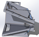
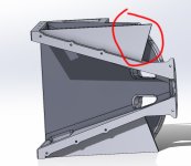
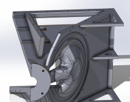
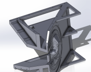
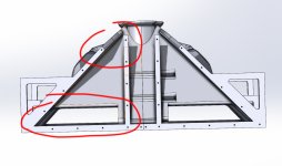
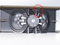
Am I crazy for thinking the reflex ports are either too big, or are being throttled in performance by the interior bracing geometry? I definitely haven't read every post in this thread but I have read a lot of it, and searched a bit for an explanation. Sorry if this is a basic question but if the air being pushed in/out of the reflex ports is being driven by the 10" drivers, through the interior bracing geometry, is that a consideration when designing the reflex port size? The holes created by the top/bottom braces are way smaller than the actual holes in the horn.
The shape of the triangle that braces the top and bottom of the horn against the cabinet differs from build to build, and I am referencing the onshape from finbot and the mrspeakers' solidworks file as well as the large folder someone assembled of everyone's build pictures. It seems changing the size and shape of this single piece would affect the amount of air that can squeeze through that opening. In the last image highlighted in blue there is a fillet on an interior edge almost like this was a consideration. The images are all from mrspeakers' file.
Is this sort of feature a negligible consideration?
Attachments
-
 415985789_775279721114809_6073685672769209396_n.png110.7 KB · Views: 226
 -
 Untitled-2.jpg75 KB · Views: 207
 -
 415851043_1305492926814613_6171095981378379693_n.png254.3 KB · Views: 194
 -
 415693850_926867028442451_145033087888210947_n.png237.6 KB · Views: 203
 -
 2.jpg134.3 KB · Views: 219
 -
 1.jpg167.8 KB · Views: 233
Last edited:
No, you are not crazy thinking the reflex ports are too big 🙂Am I crazy for thinking the reflex ports are either too big, or are being throttled in performance by the interior bracing geometry? Sorry if this is a basic question but if the air being pushed in/out of the reflex ports is being driven by the 10" drivers, through the interior bracing geometry, is that a consideration when designing the reflex port size? Is this sort of feature a negligible consideration?
The triangular inner port sides are the left and right sides of the adjustable pole mount, missing in the pictures you posted. On the top, those port sides you referred to as braces, are duplicated, the volume between them left open to the box interior. The left and right horn walls make the outer port sides. The horn sides are cut down close to the 10” drivers.
The port entrance cross sectional area and exit are roughly similar.
The large enclosed port volume and length required a very large port exit to achieve the Fb (box tuning frequency) of ~81 Hz (the low E on a guitar).
The large port volume and cross sectional area also results in large port resonant peaks (pipe resonance) at 335Hz and 634 Hz seen in this port exit trace:
The upper pipe resonance is out of phase with the 10” horn output, causing a narrow cancellation at 700Hz. Ground plane test at two meters from the secondary horn mouth, green trace is the sealed response, blue ported:
In retrospect, the 3dB gain the ports provide around Fb are probably not worth the -3dB 350 to 475Hz and-10dB cancellation at 700Hz. That upper cancellation requires more output from the HF driver to “fill the hole” in response they cause. Most 3" diaphragm drivers are already excursion challenged in the acoustical crossover range.
To sum up, don’t bother with cutting the port holes, leave the cabinet sealed 😉
Art
Thank you for the clarification and corrections, I appreciate how active you are in this thread in general, you have given many very helpful and insightful replies.
Since 3d printing the horn has been done by a few different people in this thread, I wonder if you would change anything about the design (ports or otherwise) if you could design it for a 3d printer? If you aren't limited by flat pieces of wood and can basically draw any kind of shape, would you?
Since 3d printing the horn has been done by a few different people in this thread, I wonder if you would change anything about the design (ports or otherwise) if you could design it for a 3d printer? If you aren't limited by flat pieces of wood and can basically draw any kind of shape, would you?

Menopause,
Yes, I'd change the design, flat side conical horns are not the best for dispersion or efficiency.
Something like in post 10,202 would be an improvement:
https://www.diyaudio.com/community/threads/acoustic-horn-design-the-easy-way-ath4.338806/page-511
Definitely would revise the porting, and use better secondary horn attachment hardware.
I'd also go three way, mid cones take the strain off the HF driver and would allow real woofers in a similar size package, far more clean output could be achieved.
Art
@weltersys Do you already have something specific on mind regarding three way? I'm getting ready to do a synergy horn project and I would be happy to experiment or work on an upgrade.
Did you ever finished the build?Cool thanks, Art... The XOC1 we built is 115cm high so a little taller than the original I believe but I think you have convinced me we were going for a little too much form over function! 🙂
SynTripP on a pole seems the way to go
Ishom,
Davidsavill was "looking at building" a narrower version of the SynTripP to replace his "old customs boxes with a 15" filling in low mids, and some HF drivers doing the rest" to match the width of his subs.
He has not posted on DIY Audio since post #631, 2018-01-10, over six years ago.
Davidsavill was "looking at building" a narrower version of the SynTripP to replace his "old customs boxes with a 15" filling in low mids, and some HF drivers doing the rest" to match the width of his subs.
He has not posted on DIY Audio since post #631, 2018-01-10, over six years ago.
Art,
I am modeling out the secondary horn attachment and I am running into issues of unsolvable angles due to unit conversion rounding. Can you please tell me what the top to bottom angle ϕ and the left to right angle θ should be in the secondary horn?
Thanks
Tyler


I am modeling out the secondary horn attachment and I am running into issues of unsolvable angles due to unit conversion rounding. Can you please tell me what the top to bottom angle ϕ and the left to right angle θ should be in the secondary horn?
Thanks
Tyler
You should be able to use the angles given in:
Post #41 contains plans and a preliminary parts lists, Post #61 has the completed parts lists and assembly instructions.
Those are as accurate as I could figure with the table saw I had at the time 😉
Post #41 contains plans and a preliminary parts lists, Post #61 has the completed parts lists and assembly instructions.
Those are as accurate as I could figure with the table saw I had at the time 😉
Firstly a big thanks to Art and this community, and to MrSpeakers for the stl files for 3d printing! I realise that printing success is very much machine and operator mediated so I'm not chasing detailed settings. However, I'm very interested if anyone printing these has used different types of filament here? What I've read so far seems to favour CF PETG or possibly CF Nylon...the carbon fibre presumably for rigidity. I was considering using ASA but that may be even more difficult to avoid warping. My slightly modded Solvol SV06 plus (300 x 300) is right on the edge of being able to fit the halved horn. With full supports it ends up too big - wondered if anyone had gotten away without them...if I'm not mistaken (could very easily be mistaken lol) the overhang angle to contend with is something like 47 degrees?
Last edited:
My build took a pause due to a change of work and I moved to a new town. But now it's time to start cutting sheets and order the last things 🙂
Was originally planning to use a class H Thomann TSA4-700 for the syntripps but ive opted for class d for optimal power use and weight. I have two Crown XLS 1000 already but am I correct to assume one channel (350w 4 ohm) for two B&C 10cl51 will not do the syntripps justice? It would also be nice to have DSP built into the amps and only do flavour and room on the external DSP as mentioned before.
I have considered QSC GXD4 and Behringer NX3000D. Is the Behringer NX-series really that unreliable as internet say or is it just that there are so many out there giving the bad rep? I would hate to damage the drivers or swap amp to something not fully calibrated at an event. Are there other class d alternatives with good DSP?
I am also complementing the syntripps with 4x Keystone Subwoofers loaded with B&C 18SW115-4 if there's no better or more efficient alternatives nowadays. I will be running 2x Behringer NX6000D. From what I've gathered they produce a measured 2x2100 rms and I can accept the risk of loosing two subs at an event.Thoughts or comments?
Have a pleasant week all!
Last edited:
The Crown XLS 1000 could deliver more than enough average long term power to cook two B&C 10cC51, but round 600 watts peak (49volts) peak power would be the minimum I'd suggest using if you want to reproduce transients accurately.I have two Crown XLS 1000 already but am I correct to assume one channel (350w 4 ohm) for two B&C 10cl51 will not do the syntripps justice?
Can't speak to the reliability issues and % of failures in the NX series, but the NU series did have a slew of bad diodes, one of the four I owned needed repairs due to that problem after the three year warranty was up.Is the Behringer NX-series really that unreliable as internet say or is it just that there are so many out there giving the bad rep? I would hate to damage the drivers or swap amp to something not fully calibrated at an event. Are there other class d alternatives with good DSP?
There are plenty of class D alternatives with good DSP, though my preference would be external DSP with FIR potential.
At a crossover point of ~100Hz, a single pair of Keystone Subwoofers loaded with B&C 18SW115-4 has considerably more output potential.I am also complementing the syntripps with 4x Keystone Subwoofers loaded with B&C 18SW115-4 if there's no better or more efficient alternatives nowadays. I will be running 2x Behringer NX6000D. From what I've gathered they produce a measured 2x2100 rms and I can accept the risk of loosing two subs at an event.Thoughts or comments?
The NU4-6000 or NX4-6000 can have pairs of the four outputs bridged for the same power/voltage as one side of a NX6000.
If one NX4-6000 failed, you would only loose ~2-3dB powering all four subs, if one NX6000 failed, the loss of two subs would be 6 dB.
Art
If as Art suggests you opt for the ability to do FIR filters, such DSP amps seem less common when I've gone searching and often quite expensive (eg crown i-tech). Not sure if this is helpful or not but the Dynacord L Series has FIR capability and while not class D isn't crazy heavy at 13kg. The L1300FD will do about 2x 600 watts into 4 ohms. I've not used them myself but Dynacord obviously has a good rep.It would also be nice to have DSP built into the amps and only do flavour and room on the external DSP as mentioned before.
Last edited:
Transients defines quality in my book so new amp it is then.The Crown XLS 1000 could deliver more than enough average long term power to cook two B&C 10cC51, but round 600 watts peak (49volts) peak power would be the minimum I'd suggest using if you want to reproduce transients accurately.
This got me thinking what my goal is.There are plenty of class D alternatives with good DSP, though my preference would be external DSP with FIR potential.
It is 'ease of use' at events and my reasoning was to calibrate the syntripps high/low as flat as possible in an open silent field and then on events indoor or close to obstructions have another dsp on top of that treating the syntripps as one HIGH channel pair with no filters but with EQ.
I reasoned doing this because the syntripps sum their sound by design and it would be more accurate to start from an open air calibrated flat as a single channel when I use a microphone and run around doing an automatic EQ per channel to account for a messy venue. I usually have to find a short time in silence to do this and then some manual general EQ on the tablet.
Maybe my reasoning is wrong?
Two things came to mind:
1.) As I have had huge success using RTA/microphone with dbx pa2 for channel EQ I want to continue doing room sweeps in this style. My fear is it will unbalance the syntripps drivers during the process and either create worse sound or a dangerous EQ for the B&C 10cl51 or celestion compression driver. Thoughts?
2.) I am not so familiar with FIR so I'll have to read up on it. Is it something replacing traditional crossover filters between the three drivers? What would you recommend my approach to be given I use a pair of syntripps and keystones and I want in a quick way on new locations from a tablet or laptop measure the sound from each channel and have individual EQ as flat as possible and then be able to manually adjust general EQ on top of that.
Very good feedback! Any other benefit or drawbacks or is it just redundancy for a little more money?At a crossover point of ~100Hz, a single pair of Keystone Subwoofers loaded with B&C 18SW115-4 has considerably more output potential.
The NU4-6000 or NX4-6000 can have pairs of the four outputs bridged for the same power/voltage as one side of a NX6000.
If one NX4-6000 failed, you would only loose ~2-3dB powering all four subs, if one NX6000 failed, the loss of two subs would be 6 dB.
Art
6 hours ago I was pretty sure what I was ordering. Now Art threw a rabbit hole at me so I know nothing again :-DIf as Art suggests you opt for the ability to do FIR filters, such DSP amps seem less common when I've gone searching and often quite expensive (eg crown i-tech). Not sure if this is helpful or not but the Dynacord L Series has FIR capability and while not class D isn't crazy heavy at 13kg. The L1300FD will do about 2x 600 watts into 4 ohms. I've not used them myself but Dynacord obviously has a good rep.
Thanks for the tip, might look into that one once I wrap my head around FIR.
- Home
- Loudspeakers
- Multi-Way
- SynTripP: 2-way 2-part Virtual Single Point Source Horn