
Wow real impressive indeed! But show us higher frequencies. 10k 20k Thats where 3pc should shine. Maybe 20Hz to see how the smps is dealing. Great great work though🥂
I've been playing with 3 pole in simulations after finding this thread. I didn't see much of a change at 20kHz... but then realized there is a pronounced change at 10kHz. The distortion between 1k and 10k stays much flatter. Good for me as my hearing is good till 10kHz, but not so much at 20kHz.
I have a problem with measuring low thd at 10kHz. Cosmos ADC is optimized for 1kHz, at 10k(20k) it has "weak" performance. In conjunction with the Topping D10s I can measure -128dB@1k, but only -114dB@10k (unbalanced, stereo mode, input range 1.7Vrms). It's a little better with the Viktor1k analog generator, -117dB@10k


I didn't see much of a change at 20kHz...
But there it is. (connect compensation capacitor instead of vas to predriver like fukamp has)
20k loopgain (CLG 30dB):
2pole TMC 65dB
3pole TMC 85dB
What does that mean? 0.001% is below audibility. Amps only have electronic performance - the speakers might have "sound performance"...Personally, I don't care if the amplifier has a distortion of 0.001% or 0.00008%, the sound performance is more important.
Many amplifiers have a bad enough frequency response to audibly change the sound, particularly with a loudspeaker load.
Well an amp with 0.001% distortion likely has a resistor feedback network and a very flat frequency response because of this.
Many of them have an inductor in series with the output, and there is often some sort of built-in low-pass and high-pass filter. You don't need much to get frequency response errors greater than 0.2 dB.
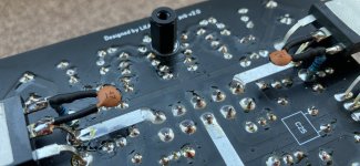
Why are the gate dampers connected to the power rails and not to GND?A mosfet version with error correction
C8 is very small capacity; in practice, it may turn out to be less than the capacity of the board when doing amateur radio soldering on this board.
Last edited:
C8 - 2p2
"Why are the gate dampers connected to the power rails and not to GND?"
a/ recommended by Bob Cordell
b/ easy to implement right on the mosfet case (short wiring); in series 47R/0.4W + 47p/250v + 47R/0.4W
"Why are the gate dampers connected to the power rails and not to GND?"
a/ recommended by Bob Cordell
b/ easy to implement right on the mosfet case (short wiring); in series 47R/0.4W + 47p/250v + 47R/0.4W
Attachments
Last edited:
Yes, this is a small capacitance rating in the negative feedback circuit, commensurate with the capacitance of the amateur radio mounting of the board, which will be added to this capacitance.C8 - 2p2
In some cases (in general), an increase in capacitance in a given circuit can lead to instability of the amplifier.
You have a feedback resistor Rf2 + Rf3 divided precisely to reduce parasitic capacitance, but all its advantage is eliminated in parallel with this chain of R39C8.
Without this capacitor, is the circuit unstable?
2p2 I imagine is to tune transient behavior by adding a subtle low pass filter. Itll cost a little bit of gain margin. Is Rf not split to reduce resistor distortion? As R can vary with voltage and temp. Nice implementation of EC! I like how u biased it. In what software did u do pcb's? I never figured out howto do flooded tracks.
Hi LKA, Is the Mosfet version simulated only? Or have you built it? Based on post #76, looks like its been built. How do you like it compared to the original bipolar version?
Hi, just a simulation for now. However, this EC mosfet output stage was already built into another amplifier.
#76 shows different mosfet amp
"Without this capacitor, is the circuit unstable?"
I haven't tried, it would probably be stable.
"In what software did u do pcb's?"
Sprint-Layout 6
#76 shows different mosfet amp
"Without this capacitor, is the circuit unstable?"
I haven't tried, it would probably be stable.
"In what software did u do pcb's?"
Sprint-Layout 6
Last edited:
- Home
- Amplifiers
- Solid State
- Three-pole compensated blameless clone