Not sure how you mean with blocking the sides? My frames are font and back of the plate only, covering about a cm around the plate, but the sides are open.
Frame does not seem to affect the sound hardly at all apart from the clamping effect similar to if you just hold on the the plate a bit with your fingers. It will improve bass response a bit.
Got the parts printed to assemble a test plate with my updated design and will take some pics when that is done.

Did some sweeps in REW with the X32-4 panels. Both are using the provided VHB tape, and mainly wanted to look at differences between the suspended and free exciters. Unfortunately I did also change position of the plate suspension a little bit, which muddies the result.
First here are som pics of the panel with grill and suspension of the exciters:


And here are the TPU pads holing the pate in place:

It was a bit tricky to get the backplate with cabling in place so had to make a desperate solution with zip ties, but know to assemble them in the opposite order next time so I can make it tidy.
FR is not looking that good though. I already noticed with the first test plate I made without the suspension of the exciters that they where lacking below 150Hz, and suspension did not seem to help. In fact the suspended plates are worse, but that could also be down to the fact that the free exciter plates have been conditioned, or that I moved the plate suspension about 7mm towards the centre of the plate.
Started conditioning the new plate and will measure again later and see if that makes a difference.
The suspended plates generally have more uneven response, but does sound better to my ears. Using glue instead of VHB tape should improve the HF response a little, but not sure what I can do about the lack of response below 150Hz.
I have not had that problem on any of the plates using the Daytons, so I suspect that it could be due to stiffer suspension on the Xcites, in which case some more conditioning might help a bit. Or it is the change to plate suspension, so will test some changes to that. My subs will handle 150Hz without problem, and the plates does sound great despite the rough response, especially with some EQ, so I guess I can live with it.

Distortion looks very good though:

And even better on the suspended version:

First here are som pics of the panel with grill and suspension of the exciters:
And here are the TPU pads holing the pate in place:
It was a bit tricky to get the backplate with cabling in place so had to make a desperate solution with zip ties, but know to assemble them in the opposite order next time so I can make it tidy.
FR is not looking that good though. I already noticed with the first test plate I made without the suspension of the exciters that they where lacking below 150Hz, and suspension did not seem to help. In fact the suspended plates are worse, but that could also be down to the fact that the free exciter plates have been conditioned, or that I moved the plate suspension about 7mm towards the centre of the plate.
Started conditioning the new plate and will measure again later and see if that makes a difference.
The suspended plates generally have more uneven response, but does sound better to my ears. Using glue instead of VHB tape should improve the HF response a little, but not sure what I can do about the lack of response below 150Hz.
I have not had that problem on any of the plates using the Daytons, so I suspect that it could be due to stiffer suspension on the Xcites, in which case some more conditioning might help a bit. Or it is the change to plate suspension, so will test some changes to that. My subs will handle 150Hz without problem, and the plates does sound great despite the rough response, especially with some EQ, so I guess I can live with it.
Distortion looks very good though:
And even better on the suspended version:
Japanese DML/Flat panel loudspeaker patents - 1/? (Adding tubes to improve DML performance)
While browsing through the thread's catalog of patents, I suddenly had an idea. Japanese manufacturers have worked with flat panel speakers for several decades, and some good ideas may be stashed away in Japanese patents. A quick search in Japanese led me to several patents from a certain Katsuhiko Umeda on Google Patents. Patent no. JP2009206914A suggests adding a layer(s) of honeycomb tubes to the panel for some benefits. Namely:
Other examples discussed include:
While browsing through the thread's catalog of patents, I suddenly had an idea. Japanese manufacturers have worked with flat panel speakers for several decades, and some good ideas may be stashed away in Japanese patents. A quick search in Japanese led me to several patents from a certain Katsuhiko Umeda on Google Patents. Patent no. JP2009206914A suggests adding a layer(s) of honeycomb tubes to the panel for some benefits. Namely:
Prevent the "wrap-around" of sound waves, which causes poor low-frequency characteristics in small speakers
The patent's proposed "flat panel speaker" and "ducting system":Provide directivity in the mid-and-low frequency range to reduce unnecessary sound wave diffusion and subsequently, noise in the vicinity outside the intended area of the broadcast (outdoor concerts and annoucement broadcasts are given as examples)
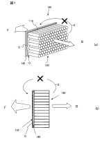
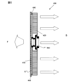
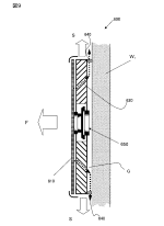
The flat panel speaker of the present invention consists of a diaphragm panel, a vibration exciter mounted on the diaphragm panel, and a number of tubes arranged through a gap against one of the acoustic emission surfaces of the diaphragm panel. The ducts are made of an elastic material that seals the gap between the diaphragm panel and the surrounding ducts.
A diffusion suppression duct device, consisting of numerous tube-like ducts, is attached to the radiating surface of the diaphragm panel with a gap. The area around the gap is sealed with a sealing material.
With this device, the air inside the duct vibrates due to the sound pressure of the diaphragm, sound pressure is introduced into the interior of the duct.
The sound waves S are reflected off the inner surface of the duct, and the sound waves that hit each other interfere with each other, similar to the effect of a common "megaphone". The ducts are parallel, thin, and long, so they do not have the effect that a typical "megaphone" has.
The sound waves are emitted from the back surface B. In this process, the sound waves are oriented in the direction of the duct.
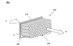
This phenomenon is similar to the principle that light traveling on the inner surface of a honeycomb core with a metallic mirror surface is directed by reflection and interference.
The tubular duct is made of a honeycomb core, and the axis of the tubular duct is formed at an arbitrary angle to the diaphragm panel. Furthermore, the axis of the tubular duct can be formed to have a focal point.
The cross sectional shape of the tubes can be circular, hexagonal, or quadrilateral.
the length and thickness of the tube must be selected according to the intended use of the speaker. If the tube is thin, reflections in the high frequency range, etc., will appear and affect the diaphragm and interfere with sound quality.
The narrower the distance between the diaphragm panels and the diffusion suppression duct devices was assumed to have a large effect, so experiments were conducted by varying the gap in various ways. In the experiment, it was confirmed that the narrower the gap, the less sound waves leaked from the gap, and thus the directional effect was greater. However, the limit is about 2 mm from the amplitude of the diaphragm.
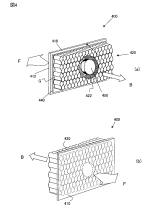
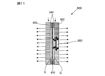
Example no. 1, a panel for listening to music:To prevent sound waves from leaking from the gap, a sponge-like material was used around the diaphragm panels to prevent the sound waves from leaking
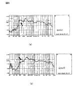
You can refer to file F1 before and after. (a) is after the modification, which significantly alters low-end performance and attenuates the mid-range. It also worsens the frequency roll-off and dip between 8-10KHz (likely due to the weight of the tubes damping the panel).The size of the diaphragm panel is 40 cm in height and 60 cm in width...the core thickness (tube length) was 40 mm and the tube diameter (cell size of the core) was 8.4 mm, with good results...The improvement was about 10db in the range of 50Hz to 300Hz.
Other examples discussed include:
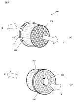
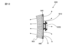
- Circular panel, 20 cm in diameter, with 80x8.4mm tubes for outdoor use (with the tubes in front and exciter in the back);
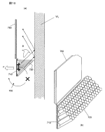
- Wall-mounted panel with the tubes angled 45 degrees from the wall to reduce wall reflections;
- More sophisticated angled tube design for a whiteboard or video screen;
- Panel used for area-specific guidance broadcasts, such as station platform guidance, with tubes on both sides;
- Curved tubes placed in front of the panel further strengthen directivity in the middle and high-frequency range.
Attachments
-
 Whiteboard-Projector Screen Panel.png17.9 KB · Views: 96
 -
 Quadrilateral tubes.png7.6 KB · Views: 88
 -
 Patent Description.png10.9 KB · Views: 81
 -
 Outdoor Panel.png16.7 KB · Views: 94
 -
 In-door Music Panel.png17.3 KB · Views: 93
 -
 In-door Music Panel cross-section.png5 KB · Views: 94
 -
 Honeycomb tubes.png7.5 KB · Views: 90
 -
 Full Tube Panel.png4.3 KB · Views: 81
 -
 Curved Tube Panel.png4.5 KB · Views: 98
 -
 F1 before-after.png14.8 KB · Views: 102
 -
JP 2009206914A patent translation.7z428.2 KB · Views: 49
-
 Wall-mounted Panel.png12.4 KB · Views: 100
Curious, that`s close to what i`m experimenting: the exciter(s) in a carved honeycomb core with several materials combined as skins, although in the back also.
Thanks for the info.
Thanks for the info.
The Honeycomb Sandwich Design has been utilised for many designs needing rigidity and lightweight. A very very fragile Honeycomb Structure, once bonded to Skins that are producing two fascia's, transforms the structural properties of each part used to produce the final assembly. The structure becomes much more than the sum of its parts used.
I believe a Aerospace Company has shown how much weight this Structure Type can take before destruction, which is usually much much more than the bulk of the guesses that have been made.
The diagrams of the Japanese Patents, all seemingly show only one face of the Honeycomb having fascia skin, which is possibly allowing for a degree of flexion, maybe the depth of the Honeycomb controls the flexion and enables a tuning of the sound.
There don't seem to be any restrictions to trialling a design, the link will show a few readily available options, the Skin Selection will also be interesting, as the Honeycomb will be offering increased rigidity so a usually rejected flimsy very lightweight material might be considered, .
https://www.plastock.co.uk/products...cjdR3XUT_heIJQCzZ8FNg_9wLxmvwelBoCCZQQAvD_BwE
The honeycomb isn't attached to the panel and is not used for creating a panel, it's used as a kind of waveguide for the sound emitted by the panel.
I believe the patent requires an air gap between the core/tubes and the surface of the panel to work. The patent notes:Curious, that`s close to what i`m experimenting: the exciter(s) in a carved honeycomb core with several materials combined as skins, although in the back also.
Thanks for the info.
P/s: what the patent considers as usable core thickness and cell size, and what happens when the latter is too small:Further experiments were conducted to try attaching ducts directly to diaphragms and without a gap, but the ducts were not effective...However, since the air in the duct vibrates together with the diaphragm and sound waves do not run through the duct, reflection and interference of sound waves do not occur, and it was confirmed that sound waves cannot be given directional characteristics...Furthermore, the acoustic characteristics in the high frequency range deteriorate due to the increased mass of the vibration system.
The results showed that the core thickness (tube length) could be reduced from 20 mm to 90 mm and the cell size from 3.2 mm to 12 mm in various combinations.
In both cases, the honeycomb core and roll core, too small a cell size (thickness of the tubing) can cause the tubing to be too thick.
Too small a cell size (tubing thickness) increased the sound pressure in the tubing and reduced the sound quality in the mid-range, partly due to interference from reflections.
Last edited:
Leob
Can you remind me of your panel dimensions and the locations of your tpu support points?
Eric
Can you remind me of your panel dimensions and the locations of your tpu support points?
Eric
The plates are 500x330mm and the support points in the latest version are located at 140mm from the edges and 20mm long.
RMAM,
I'm wondering if the material you are talking about is PMMA, rather than polyethylene. PMMA is also known as acrylic or plexiglass. Among the materials I've tested, PMMA seems to have very good internal damping (as your post suggests), based on the impedance results in the link below.
Eric
https://www.diyaudio.com/community/...s-as-a-full-range-speaker.272576/post-7499940
Valeric, it turns out to be polystyrene, more precisely syndiotactic polystyrene (sPS or PS-st) so... in the family of EPS and XPS.
The chemical world is a multiverse, my daughter told me about sPS-graft-poly(methyl methacrylate) (sPS-g-PMMA).
Still waiting for the manufacturer specs for more details.
Nidaplast!
https://www.nidaplast.com/en/products/61-nidaplast-8

But this is polyprop.
I think Podium use a polycarb version in their panels.
https://www.nidaplast.com/en/products/61-nidaplast-8
But this is polyprop.
I think Podium use a polycarb version in their panels.
LeobThe plates are 500x330mm and the support points in the latest version are located at 140mm from the edges and 20mm long.
So is it 4 points of contact then, two on each of the long sides? Or 8 (on both long and short sides)? And what is the thickness of your panel? I was thinking I might do an FEA model of your plate/mounting, just to see what the mode shapes and frequencies are. It would only be a rough approximation, as I don't know the material properties of your plates, but I can probably make a decent guess.
Eric
Thanks @Veleric that would be amazing!
It is these plates https://www.dekokopf.com/neopor-styroporplatten-3er-set-50x33x2-5cm.html
So 25mm thick.
I added hide glue and shellac and rounded the corners, mostly to make it easier to mount everything together.
I add on 2 points on each long side, from both directions, so a total of 8 pads.
Previous revision I had one point in the middle on each side, so same amount of pads, and then I got a lot better response below 150Hz...but with many other variables being different as well.
I'm experimenting with different honeycomb panels, and I get the impression that the material makes more difference to the FR than the aspect ratio/size. For instance I made a 4 mm thick panel from higher weight honeycomb nomex than my 3 mm panels, and it's bass light, and has a very pronounced and annoying peak at 3 kHz. Changing the dimensions didn't make a difference to the peak. The panels shouldn't be to stiff to get enough bass - or so it seems.
My first nomex paper panel that "sounded" really good has ridges on the surface - a random pattern of bumps because I used to much epoxy, It pooled under the paper with air bubbles in between. Could it be that that accidentaly is a good way to "randomly" dampen the panel? It still is the best effort so far. It gave an immidiate "This sounds really nice" reaction. Has anyone a clue what might be happening? I'll try to make another "proper" panel, and to mimic the ridges with a textured roller and thickened epoxy.
If I manage to get a similar sounding panel as my first one I might keep that as "the standard". This panel thing is so complex. It might be best to stick with what (found by accident) works OK.
BTW the panels I make are about 450 g/m2 now, so building lightweight is doable.
BTW II The response of the panels changes quite a lot in the first days after making the panel, because of the epoxy slowly hardening to it's end value. When cured for 24 hours there's not much HF, and the panel sounds cardboard-y. Two days later the HF by magic has appeared!
Last edited:
Andre,Nidaplast!
https://www.nidaplast.com/en/products/61-nidaplast-8
View attachment 1272671
But this is polyprop.
I think Podium use a polycarb version in their panels.
I tried buying something very similar in the US some time ago, but the supplier never had the thickness I wanted in stock, so I finally gave up. I was planning to try adding a fiberglass/epoxy or carbon fiber epoxy layers on top and bottom. I think it would have been a very efficient panel, but maybe also have been a bit too stiff. It's worth a try I think.
Regarding the podiums, I think they used a nomex honeycomb with Mylar skins, though I can't find the source of that info just now...
Eric
RMAM,Valeric, it turns out to be polystyrene, more precisely syndiotactic polystyrene (sPS or PS-st) so... in the family of EPS and XPS.
The chemical world is a multiverse, my daughter told me about sPS-graft-poly(methyl methacrylate) (sPS-g-PMMA).
Still waiting for the manufacturer specs for more details.
Interesting. PS makes more sense than PE. I would have expected it to be garden variety PS (i.e atactic) rather than syndiotactic, however. I would have thought that sPS would be too expensive to use for anything but fairly specialized applications, but I could be wrong about that...
Eric
Hello!
I am new to the DML "sport" so I've been doing some homework.
I've been through much of the pages here as well.
Now here's something I found out, that might be interesting.
There's a paper from Chalmers University of Technology:
"A critical review of bending wave loudspeaker technology and implementation
Master’s Thesis in the Master’s Programme in Sound and Vibration
KUONAN LI Department of Civil and Environmental Engineering
Division of Applied Acoustics
Room Acoustics Group
CHALMERS UNIVERSITY OF TECHNOLOGY Göteborg, Sweden 2010 Master’s Thesis 2010:9"
You can look it up, it's free to download.
In there they analyze some example DML panels and they discuss Excitation point and Geometry of Panels.
They have an example figure in which Modal Analysis is illustrated.

They comment on this:
"The position of the exciter will decide which modes of the plate will be excited, affecting the radiation performance of DML. Thus it is essential that one makes sure that the excitation point couples as many modes as possible, and ensures de-correlation between panel velocity and drive point. One might use, again, FEA to determinate the position of the exciter. Usually observing the first 20 modes or so is sufficient to conclude the optimal point of exciter, which is often near the middle point of the panel but never exactly on it. This is because that while the exciter is on the middle, it only can excite even modes. Figure 3.5 illustrates the nodal maps of the first 20 modes of a panel quoted from [9], which can be done by using FEM. The region where fewer nodal lines pass is a better position for exciter; in this case, possible choices are near the middle and the corners"
As we can clearly see, the region at the middle section (blank space, not dead center on the cross point ) provides the best possible positions for exciter placement, the edges are not considered as good choices.
Now look at this picture below.
I overplayed in red lines a Phi Matrix (Golden ratio) over the original image, just out of curiosity.
Look at this! It's a perfect match!

Hmmm! I think there's some juice here.
The picture above has the two ratios of 0.618 and 0.382 lined out.
Look at the picture below where the 5 lines of phi matrix are overlaid.

Nature works in patterns 😉 and I think there's an obvious one here.
This could possibly give us hints for better placement.
I am definitely going to try this on.
I would appreciate your thoughts or experiments on such a possibility as well.
Manos.
I am new to the DML "sport" so I've been doing some homework.
I've been through much of the pages here as well.
Now here's something I found out, that might be interesting.
There's a paper from Chalmers University of Technology:
"A critical review of bending wave loudspeaker technology and implementation
Master’s Thesis in the Master’s Programme in Sound and Vibration
KUONAN LI Department of Civil and Environmental Engineering
Division of Applied Acoustics
Room Acoustics Group
CHALMERS UNIVERSITY OF TECHNOLOGY Göteborg, Sweden 2010 Master’s Thesis 2010:9"
You can look it up, it's free to download.
In there they analyze some example DML panels and they discuss Excitation point and Geometry of Panels.
They have an example figure in which Modal Analysis is illustrated.
They comment on this:
"The position of the exciter will decide which modes of the plate will be excited, affecting the radiation performance of DML. Thus it is essential that one makes sure that the excitation point couples as many modes as possible, and ensures de-correlation between panel velocity and drive point. One might use, again, FEA to determinate the position of the exciter. Usually observing the first 20 modes or so is sufficient to conclude the optimal point of exciter, which is often near the middle point of the panel but never exactly on it. This is because that while the exciter is on the middle, it only can excite even modes. Figure 3.5 illustrates the nodal maps of the first 20 modes of a panel quoted from [9], which can be done by using FEM. The region where fewer nodal lines pass is a better position for exciter; in this case, possible choices are near the middle and the corners"
As we can clearly see, the region at the middle section (blank space, not dead center on the cross point ) provides the best possible positions for exciter placement, the edges are not considered as good choices.
Now look at this picture below.
I overplayed in red lines a Phi Matrix (Golden ratio) over the original image, just out of curiosity.
Look at this! It's a perfect match!
Hmmm! I think there's some juice here.
The picture above has the two ratios of 0.618 and 0.382 lined out.
Look at the picture below where the 5 lines of phi matrix are overlaid.
Nature works in patterns 😉 and I think there's an obvious one here.
This could possibly give us hints for better placement.
I am definitely going to try this on.
I would appreciate your thoughts or experiments on such a possibility as well.
Manos.
Eric, you are not wrong, it becomes established that they have the sheets wrong placed and priced. Meanwhile the atactic PS. with same dimensions are now playing with some more eq (i.e, less dB`s) in the 2 to 8 kHz band compared to the previous. The price diferences don`t favor the s-PS.RMAM,
Interesting. PS makes more sense than PE. I would have expected it to be garden variety PS (i.e atactic) rather than syndiotactic, however. I would have thought that sPS would be too expensive to use for anything but fairly specialized applications, but I could be wrong about that...
Eric
The honeycomb isn't attached to the panel and is not used for creating a panel, it's used as a kind of waveguide for the sound emitted by the panel.
Obviously, although you can dampen the panel attaching it to the honeycomb wich is needed depending on material type, dimensions and panel load.
Nevertheless, i think is more cost effective to add exciters on the same panel, or chose different materials/exciters for separate mid/low freq panels to achieve the same goal.
Leob,
Here is what I have so far using the LISA FEA to model your plates. There are lots of assumptions, so take it all with a grain of salt, but hopefully it's is still interesting to you.
I used plate dimensions of 550 mm x 330 mm x 25 mm, with a corner radius of 60 mm. The supports are 20 mm x 10 mm centered 140 mm from the plate edges. I assumed an elastic modulus of 30 MPa, density of 40 kg/m^3, and poisson ratio of 0.3. Those came from some EPS I tested before.
Images below show the estimated frequencies and mode shapes for the first 15 modes.
Based on the mode shapes, the ones I would expect to radiate sound best would be: 1,3,8,9 and 12.
Eric
- Home
- Loudspeakers
- Full Range
- A Study of DMLs as a Full Range Speaker