There's also the 6/38/40KD6's. Not quite as robust as the 6LF6 but close.
Maybe cheaper and more readily available. I've several I think. These tubes
were paralleled sometime 8 or more in HF linear amps during the CB craze in the US.
The 6LQ6 was also used in a lot of those amps. Always ran grounded grid.
Maybe cheaper and more readily available. I've several I think. These tubes
were paralleled sometime 8 or more in HF linear amps during the CB craze in the US.
The 6LQ6 was also used in a lot of those amps. Always ran grounded grid.

Nice find!I just found a RCA datasheet of the 6JE6A, a 30W Pa horizontal sweep tube, it actually has a design center dc voltage of 990V for the anode, peak pulse voltage is with 7.5kV about similar to the pl509, 519
Jan
I think the 36KD6 is used in the beveridge amp.There's also the 6/38/40KD6's. Not quite as robust as the 6LF6 but close.
Maybe cheaper and more readily available. I've several I think. These tubes
were paralleled sometime 8 or more in HF linear amps during the CB craze in the US.
The 6LQ6 was also used in a lot of those amps. Always ran grounded grid.
Jan
Jan - What is a suggested max heating power? Thus far, I've found just under 50 that roughly meet your quoted min plate voltage and power but with considerable range of filament power consumption. If you wanted to take up pottery with your own kiln there are some that could help you along.
Attachments
I don't have a specific aim aside from 'as low as possible'.
Heater power would be a secondary requirement, the primary being 80W Pa (possibly two 40W in //) and 8kV max peak Vak.
I also would prefer a (beam) triode to avoid the complications of a G2 supply and possibly G2 arcing.
That 5946 looks interesting, appreciate the help!
Jan
Heater power would be a secondary requirement, the primary being 80W Pa (possibly two 40W in //) and 8kV max peak Vak.
I also would prefer a (beam) triode to avoid the complications of a G2 supply and possibly G2 arcing.
That 5946 looks interesting, appreciate the help!
Jan
I worry about sweep tubes for your use. Their peak voltage ratings are based on pulse conditions, and are anyway exceeded, or at least stretched, in your use. Their high perveance and big space charge come with a big heating power requirement, and is wasted in this use (they're almost turned off).
Sounding like a broken record, a transmitting valve is called for here, I'd submit. Something with a cathode surface designed for the 4KV anode voltage ion bombardment and an overall structure designed for 4KV all day every day. OK, I'll shut up about it now.
All good fortune,
Chris
Sounding like a broken record, a transmitting valve is called for here, I'd submit. Something with a cathode surface designed for the 4KV anode voltage ion bombardment and an overall structure designed for 4KV all day every day. OK, I'll shut up about it now.
All good fortune,
Chris
Earlier today I went down the CV list on Frank's site and focused only on power triodes (capital T) . Out of the 50 or so that can accomodate the high anode voltage, many had filament power demands that I had to assume are out of the question.
You might take a look at CV's - 28, 62, 92, 199, 240, 381, 446, 570, 1090, 1207, 1253, 1254, 1256, 1610, 1614, 1617, 2163
Many of these have equivalent numbers posted next with graphic data but the CV sheets mostly have the same layout so once you're used to them it's very quick to scan for the numbers you're interested in.
There are also some nice looking water cooled beasts around . : )
Attachments
That's a great overview! I did a quick look and see some promising tubes.
I'l take some time to put them in a spreadsheet for comparison.
I haven't checked availability and prices; I would need half a dozen.
Also it is not clear how I should mount them, but that's for later.
Jan
I'l take some time to put them in a spreadsheet for comparison.
I haven't checked availability and prices; I would need half a dozen.
Also it is not clear how I should mount them, but that's for later.
Jan
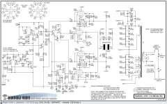
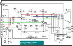
Jan check this schematics , since maybe this can be useful for your project , basically it represents principle how CRT cathode is linearly modulated with wide band video signal in countless nr. of colour TV set`s ,notice that there`s allways present one cathode very clean bias positive DC source , we R&TV repairsmans called that source simple as
the question is ; for your specific hybrid amp and for linear cathode drive but now with audio signal it is also necessary to have some suitable DC bias source or not ?
200V line , principle is very simple , when video signal is not present on the driver transistors base than the driven cathode current is Ik=0uA , CRT screen is black , that also mean that cathode now stays on max.DC positive potencial relative to g1 which is grounded , that represent cutt-off point ,the question is ; for your specific hybrid amp and for linear cathode drive but now with audio signal it is also necessary to have some suitable DC bias source or not ?
Attachments
Last edited:
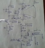
Post # 135 shows my concept. No additional bias supply is needed.
I think it is similar to what you show.
Jan
I think it is similar to what you show.
Jan
Ahh, missed that, so quiescent Vp is only 3600VDC? That might allow for a few more on the list.Post # 135 shows my concept.
Paralleling PL519 tubes would be the most interesting as these are available and affordable. Nice for experimenting.
7,5 kV should be about the max they can handle.
Why the need of increasing the voltage as i found that 3kV is more then enough to shake the house (concrete walls).
7,5 kV should be about the max they can handle.
Why the need of increasing the voltage as i found that 3kV is more then enough to shake the house (concrete walls).
Last edited:
Yes, but the inductive load will make the anode swing up to double that, in theory to 7200.Ahh, missed that, so quiescent Vp is only 3600VDC? That might allow for a few more on the list.
Is that implied/allowed in the '3500 VDC' spec?
Jan
So you will need an inductor that can handle the same voltage and current.
@Lampie519 I have dismissed the PL519 family earlier because of low Pa, but yes two in // could just about cut it in my app (10mA at 3600V quiescent).
But the need for a G2 supply is a complicating factor in my design (details later) so I would prefer a triode or beam triode.
But I'll keep it on my shortlist.
Jan
But the need for a G2 supply is a complicating factor in my design (details later) so I would prefer a triode or beam triode.
But I'll keep it on my shortlist.
Jan
Are the big HBI-2B tubes too much or otherwise have an inappropriate spec for your application? Anode voltage 32 kV, Grid two 2 kV, Grid one 600 V. Did I read somewhere Pa is 900 W? They sure look cool:
https://soviet-tubes.com/product/gmi-2b-tetrode/
https://soviet-tubes.com/product/gmi-2b-tetrode/
I do not have experience with tubes used in these voltage ranges , but in the little world I know the max voltages are given for steady state / quiescent or design centre operation unless specified otherwise. It's expected that with an inductive load , the voltage can swing up to 2x B+.Is that implied/allowed in the '3500 VDC' spec?
Until now I'd have assumed that industry nomenclature would be consistent across the board. Some of those sheets do make a distinction between max and max pulse or peak, but it's worth being absolutely sure.
I just sent an email to a vendor who should be able to confirm one way or the other.
If it's 100% sure that a 4KV max means it's safe to swing to 8KV unless specified on the sheet, things open up quite a bit.
A bit of a different animal built for RF. Used in Swan and Siltronix amateur radios.
Very tough tube.
https://frank.pocnet.net/sheets/084/8/8950.pdf
Very tough tube.
https://frank.pocnet.net/sheets/084/8/8950.pdf
I made a rudimentary inventory as attached. It seems that the CV-1256 and its siblings are the most promising.Earlier today I went down the CV list on Frank's site and focused only on power triodes (capital T) . Out of the 50 or so that can accomodate the high anode voltage, many had filament power demands that I had to assume are out of the question.
You might take a look at CV's - 28, 62, 92, 199, 240, 381, 446, 570, 1090, 1207, 1253, 1254, 1256, 1610, 1614, 1617, 2163
Many of these have equivalent numbers posted next with graphic data but the CV sheets mostly have the same layout so once you're used to them it's very quick to scan for the numbers you're interested in.
There are also some nice looking water cooled beasts around . : )
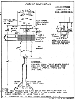
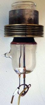
What I am wondering is the mechanical mounting of the tube. Am I right that the grid is in the center connected to a threaded insert.
How would I mount this tube on a chassis of some sort?
Jan
Attachments
- Home
- Amplifiers
- Tubes / Valves
- Looking for high-voltage tubes