So, while I had the PD510 still on the bench, I measured some working points in A2:.Jan, If i where you, I would just take one of those TV shunt stabilizer tubes to find out how suitable they would be for the task.
Build a fullwave voltage multiplier with some 400-550V CT transformer.
Hook up the tube with adjustable positive grid voltage, adjust necessay positive gridcurrent till max anode dissipation at the different high voltage steps you get from the multiplier.
DC link caps and avalanche diodes like the BYW96 are your friends.
The first cap of each halfway multiplier side could be taylored to limit the max short current .
Then one can safely climb up the ladder tubelabs style till the tube pops or sensible gridpower is exceeded.
I would thinck something up to 100mW on the grid is something just about any tube can take.
At 600V anode, it took +9.8 V and 6.77 mA into the grid to get 6 mA anode current.
I could not double the current by turning up the grid voltage, at this anode voltage.
At 1000V anode, it took +12.2 V and 10.8 mA into the grid to get 10 mA anode current.
This was measured with screen connected to the cathode.

Very interresting. Was that 10mA Ia at 1000V the max you where able to get even with increasing grid power, or did you just not want to take risk it?So, while I had the PD510 still on the bench, I measured some working points in A2:.
At 600V anode, it took +9.8 V and 6.77 mA into the grid to get 6 mA anode current.
I could not double the current by turning up the grid voltage, at this anode voltage.
At 1000V anode, it took +12.2 V and 10.8 mA into the grid to get 10 mA anode current.
This was measured with screen connected to the cathode.
Could you make one more measurement at 1000V anode? What would be needed at the grid to get the same anodecurrent, of 6.77mA, that you had with 600V. Or, what would even be better, some higher than 1000V on the anode, but same 10mA anode current? Should the required grid power go down then i could see some hope for sucess with this tube
Would also be interresting to see what kind of difference grid and screen connected together would make.
Last edited:
This may be the most useful tube found yet, needs paralelling offcourse, but would be easy to driveWould parallel tubes for the required current work? Thinking tubes like the 2c53 or 7235 . Heater current for five 2c53 in parallel is still only 1.5A.
My reasoning went as follows:Very interresting. Was that 10mA Ia at 1000V the max you where able to get even with increasing grid power, or did you just not want to take risk it?
Could you make one more measurement at 1000V anode? What would be needed at the grid to get the same anodecurrent, of 6.77mA, that you had with 600V. Or, what would even be better, some higher than 1000V on the anode, but same 10mA anode current? Should the required grid power go down then i could see some hope for sucess with this tube
Would also be interresting to see what kind of difference grid and screen connected together would make.
1. I performed the first measurement at 600V but couldn't get the desired current.
To figure out whether the cathode is just too weak, or there is another limit, I increased the anode voltage by adding a second bench supply in series.
2. At 1000V, I stopped at 10 mA because it was already more then I could achieve at 600V and thus made me conclude the cathode might be strong enough.
I didn't perform more measurement in this configuration however, because I believe this tube is not suitable for the OP's needs;
If it cannot pass the desired max current of 25mA at relatively low voltage of 600V, it's just not going to work at the desired operating point, is it?
Yes, I would thinck so too, cathode emission will not be the limit.
Maybe Jan could try with his 4kV PS what anode voltage is required to get 30W anode dissipation with kathode and grid1 and screen shorted.
Could be worth also to try a bit of positive voltage on the screen grid, or drive g1 and screen together.
Or, if you want to risk it, you could try how much the grid really can take.
The screen on PD500/PD510 is not really like a classical screen grid.
See drawing here http://www.kronjaeger.com/hv-old/xray/tech/PD500/ and pictures http://www.r-type.org/exhib/aah0027.htm.
But hey, one doesn't know until he tries. Maybe I'll try later today with 600V anode and positive voltage on screen.
See drawing here http://www.kronjaeger.com/hv-old/xray/tech/PD500/ and pictures http://www.r-type.org/exhib/aah0027.htm.
But hey, one doesn't know until he tries. Maybe I'll try later today with 600V anode and positive voltage on screen.
Thanks, yes this seems a dead end.So, while I had the PD510 still on the bench, I measured some working points in A2:.
At 600V anode, it took +9.8 V and 6.77 mA into the grid to get 6 mA anode current.
I could not double the current by turning up the grid voltage, at this anode voltage.
At 1000V anode, it took +12.2 V and 10.8 mA into the grid to get 10 mA anode current.
This was measured with screen connected to the cathode.
Jan
These would be ideal if not for the limited Pa. I need 80W total so that would mean 7 or 8 tubes in parallel ...This may be the most useful tube found yet, needs paralelling offcourse, but would be easy to drive
Jan
How do you plan to avoid the dreaded runaway with 6LF6 and GMI-11 at these high voltages?
Connect the screen to cathode and hope it doesn't arc over to the anode?
Connect the screen to cathode and hope it doesn't arc over to the anode?
Well they are specified to 10kV or 8kV so I assume there will not be arcing.
The runaway is absent by design.
Jan
The runaway is absent by design.
Jan
JanI think I will order a couple of the 6LF6 and GMI-11 and do some experiments.
Jan
that`s just OK to made experiments with those tubes and to see the results , but IMHO you should not ignore those 2C53 triode tubes , since their overall characteristic is very interesting for one simple HQ- ESL-OTL -AB1 class full tubes amp , only drawback is that you will need about three or four 2C53 tubes per PP side , but one of the advantage is that you can drive them very easy with one more double triode such is let`s say 6SN7 or 6SL7 tube .
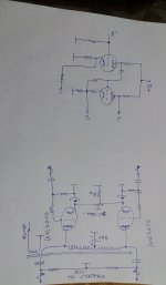
Attachments
Re-reading it, I guess you mean arcing between G2 and A?How do you plan to avoid the dreaded runaway with 6LF6 and GMI-11 at these high voltages?
Connect the screen to cathode and hope it doesn't arc over to the anode?
Jan
As much as I love this attempt at being practical in audiophile madness, and I do, I really do...
At a certain point the speaker itself will arc over, regardless of how robust the driving amp is. I'm remembering early electrostatic reviews done in Santa Fe where the increased altitude alone caused trouble.
I do not know those limits in a '63 and I do not know how much beyond stock a superamp like this might push a '63. But for sure there's limit somewhere and way out at the boundaries where this project lives, this represents a non-negotiable limit.
(Unless your name is Michael Dayton Wright, then you find another answer lol)
I don't remember the exact figure for the protection setting in the '63 but I believe it is 10kV, single ended.
Jan
Jan
It is indeed one of my worries.Re-reading it, I guess you mean arcing between G2 and A?
Jan
I was looking at local surplus shops, and found this type: 8068
Unfortunately, out of stock!
I just found a RCA datasheet of the 6JE6A, a 30W Pa horizontal sweep tube, it actually has a design center dc voltage of 990V for the anode, peak pulse voltage is with 7.5kV about similar to the pl509, 519
- Home
- Amplifiers
- Tubes / Valves
- Looking for high-voltage tubes