Any suggestions on which transformers to use for this use case? So that a transformer can power more than one UCPure. That we the cost would be down and more importantly the space would be manageable.Looking at this more closely, this is a center tapped transformer so it is not intended to be used to power two independent PSUs. It could, but they would not be independent from each other. UCPure needs to use separate power supplies. So you either need another transformer or one with independant secondaries.
Great stuff, Lso!
Have you seen any value in the MonitorPi Pro? Do you use it just as a display or also as a functionality controller?
And another question. How happy are you with the overall sound quality?
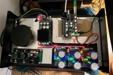
With the very kind help and persistence of @Chris1967, I've finally figured out the problem with my Ian Canada streamer and GentooPlayer. It was a hardware problem with the StationPi Pro, after all. Once that got out of the way, my streamer is now working fine with GentooPlayer (see photo). I will be expecting a replacement StationPi Pro Ian and hopefully be able to complete my streamer project soon.
Oh yes, I have also ordered a MonitorPi Pro, so that I will be in a position to monitor and also control the streamer.
From then on, I will see whether I can further improve the sound quality as much as possible. Any comments are most welcome, of course.
Attachments

Can you or somebody else please tell us what the hardware problem is from the StationPi Pro?
Regards,
Rudy
Regards,
Rudy
Hello,
Digital audio made things easier?
Gabsters cat walking across a bunch of ultracaps. The clocks should be powered on 24/7. I wonder how other members did organize their things. I already wrote months ago if your neighbours toddler enters your house with a metal toy, get attracted by the Canadian Christmas decorations ( like we do) and starts poking around. But people here don't realize what these caps can cause when short-circuited.
Greetings Eduard
I am also building a TDA1541A Dac @Gabster 2000 🙂 I am using 4 of the ICs and using Ians modules. Thanks For you video as it was great to hear your feedback
If you look at the schematics the two secondaries are independent and not Center tapped. A Center tapped transformer would only have 3 wires on the secondary side a properly listed something like 12-0-12 v.Looking at this more closely, this is a center tapped transformer so it is not intended to be used to power two independent PSUs. It could, but they would not be independent from each other. UCPure needs to use separate power supplies. So you either need another transformer or one with independant secondaries.
@NeoTheOne
If you have a MonitorPi Pro or a Q7 you can use the SYNC control to change multiple UcPure at the same time.
This would load the two secondaries evenly, if you would proceed with the transformer you previously linked to.
Hello,
If you have two ucpure circuit and one of them has to deliver twice as much current once they start charging will the two charging current be identical?
Of course on the ucpure board you can choose the lower charging current. Can also decide to go for a different transformer!
Gabster is also not using the transformer according to the datasheet. But it could be that the cat pulls some strings before it goes wrong. Cat have multiple lives they say.
My 4 year old nephew put a hair pin into the 220 volts outlet a few decades ago when security concerning household electricity was close to non existent. He survived.
Greetings Eduard
Be careful with the transformer output voltage as if too high it can blow up the ucpure as it happened to me
you need to consider the ac voltage will raise once the caps are charged so consider it all
you need to consider the ac voltage will raise once the caps are charged so consider it all
@wcwc mentioned Antek transformer would be safe to use in this way. I'm thinking about this one - AS-1212 - 100VA 12V TRANSFORMER .
In most builds I see the secondary of the transformer directly connected to the UCPure input. What can be used to make sue the UCPure does not blow up? Btw, did the circuit board blow up or the capacitors themselves?Be careful with the transformer output voltage as if too high it can blow up the ucpure as it happened to me
you need to consider the ac voltage will raise once the caps are charged so consider it all
As i said here https://www.diyaudio.com/community/...eapon-to-fight-the-jitter.192465/post-7571056 i suspected the pins on the Station Pi Pro, because i have identical system (except Hdmi Pro instead of Spdif) , and have a fair knowledge of Gentooplayer.Can you or somebody else please tell us what the hardware problem is from the StationPi Pro?
Regards,
Rudy
I tried the pins for continuity and found that not all of them have. It seems to me there are dry joints on the smd pins. Furthermore, there seems to be a small "blob" between two traces at the back.
Ian responded promptly and helped us troubleshoot, namely use the rpi stack method and not Station, and use Volumio setup that is known to work.
It is a little odd everyone here thought it was the Gentooplayer or spdif incompatibility.
In any event the problem was solved, thanks to Ian!
Ian updated the manual once I told him by recommending Lower AC output voltage. The issue was ucpure stopped charging and only way I saw this problem@wcwc mentioned Antek transformer would be safe to use in this way. I'm thinking about this one - AS-1212 - 100VA 12V TRANSFORMER .
In most builds I see the secondary of the transformer directly connected to the UCPure input. What can be used to make sue the UCPure does not blow up? Btw, did the circuit board blow up or the capacitors themselves?
Hello,I tried the pins for continuity and found that not all of them have. It seems to me there are dry joints on the smd pins. Furthermore, there seems to be a small "blob" between two traces at the back.
Should we check our boards for dry joints after receiving them?
I would rather pay extra to get a checked board so i can be sure that the reason for no sound is not related to a blue monday in a far away country.
Especially for the people who dont wanna inhale soldering fumes every evening after a hard days work getting checked boards will be a big plus so you could get your stack mounted on a Saturday morning.
Greetings,Eduard
What an impressive job. Thank you for sharing.My Best Effort As The Do-Everything-A-Little-Right Ian Canada Build
This is so far, the whole build will be moved and live in a custom grainte case I am having made for me. This weighs 80lbs as is, without the added grainte
1.Everything is grounded. Like everything. Every Positive lead has copper foil added to it with a ground wire to ground bus bar, then added PVC tape or PTFE tape depending on importance of that lead (leads to UCpure do not need PTFE for example)
2. Star ground internal system, which is best, then to a dedicated home audio grounding system.
3. Every wire, every pin, every contact, every piece of everything that is connected, and I mean everything, was treated with deoxit red multiple times using a dremel, then deoxit gold if it was a gold contact or pin, then deoxit blue for shield. I got every single connector as shinny as jewerly. Every UCpure screw even. If it touches a wire or a contact in any way, shape, or form, it was treated.
4. Everything has its own dedicated copper plated enclosure (Pics show rpi in its own, the top all has their own as well, however not pictured here). Everyone is grounded with their own home run to the internal copper bus bar (that was also treated with deoxit) to create a true star ground. You dont want to share grounds until the end. It makes a difference.
5. Everything is on their own layer of sorbothane for vibration
6. Every copper tube is on sorbothate. The Toroidy transformer is on its own sorbothate. Sorbothane everywhere, everything can transmit vibrations, any wire in our out of anything. The IEC is on sorbothane for inlet AC power cord vibrations!
7. There is sorbothane between top and bottom rack, without any screw for physical connection (would transfer vibrations)
8. Every wire is run thru copper grounded tubing, wires that are not are ground wires
9. Extra white wires are for all the top grounding enclosures and wires (not pictured)
10. Inlet IEC is pure copper and treated with deoxit
11. Inlet cabling is 12 guage solid core pure copper, in aluminum conduit, grounded, further shielded with copper thats grounded
12. All wire for power supplies and supplies to Ian parts is pure copper, sold core, 14 gauge, in PTFE, wrapped with additional copper foil layer thats grounded, with final layer of skived PTFE tape (skived is the real deal PTFE)
13. 0.5" very heavy aluminum panels are used between top and bottom layer, they are epoxyed into the top layer. There is then individual bottom copper plates, which are all grounded, on the top.
14- SC-Pure clock pins treated with deoxit red, yellow, blue with dremel shinny as can be. Held secure with tack around the base of the clocks for snug fit and then added sorbothane layer ontop of the clocks. I even dexoit treated the little master clock cable, lol.
14. The entire 80lb frame as pictured sits on 3 5" in diameter 1" sorbothane doughnuts for final build to rack isolation.
(I need to still copper cover and ground the monitor pi pro...temporary location in pics)
I measured almost ZERO EMI or RF, no matter where you measure around the gear, top, bottom, near any wire, any item, the pi, the dac stack, ect. My EMF, even using the Toroidy power supply (dedicated electrical shields between each output that are grounded individually, added EMF shielding, in epoxy, and then stainless steel enclosure for EMF I can measure 300-400 on my EMF meter. Now, directly above it (measure highest EMF directly above a toroidal) with the aluminum and copper, I measure down to 10 or so. This drops off to 2-3 once you move very slightly from dead center above.
If I disconnect the ground from the copper bus bar (out with 16 cable OCC braided cable to Gr research Tube connector) to the audio dedicated ground system I can measure 300-400 for EMI and RF all over the board. Even when the Ucpure is in "pure" mode the AC lines without the above grounding steps are measured in the 200's. Connect the ground back...boom almost 0 everywhere.
I think I thought of everything you can. I run audiolinux on my rpi5 and thats a whole talk in itself as how much my audiolinux server and audiolinux pi are tweaked to perfection. My networking is all home clocked on GPSDO OCXO and I made every xlr and cable, with OCC copper braids, added foil, ptfe layers, and repeated multiple times, each layer with their own dedicated grounds. I use a Lush^3 USB cable which is killer for Pi to DDDC which I can lift grounds, one side ground, both, connect shields in parallel, series, ect
I dont think I can really think of what else I can do. It will look very nice and high end once its in my custom CNC granite case.
I thought about added shielding between layers of all the Ian parts, but I dont think it is needed here. I cant measure any EMI or RF around or between any of the boards. This is likely due to everything being grounded already and noise from the stack goes out via its grounding.
I spent a LOT of time laying out this build, thinking of everything, measuring, moving things, testing testing testing. I can tell you all of this work IS WORTH IT and the sound compared to my video showing the test build is VERY REAL and this thing sounds WOWOWOWOW....without any wire burn in either.
PS - Don't mind the mess and random HDMI cable that normally is not there, I just was excited to get it playing again after 3 weeks of many many many hours spent getting from test bench build to this.
Hi, can anyone help me understand how to power the adapter board for the rfx ocxo(s)?
I could not find instructions, or manual. I am planning the power supplies at this early stage. The clocks seem to take 5 v each. But the adapter board has two sets of + & - for each clock, which has me confused. I had hoped to use Allo Shanti for the two clocks, but need to make sure I know what the adapter requires.
My plan was to put two of the super capacitor packs into a separate enclosure, and use these for the fifopi Q7 and the dual mono dac. I already have some lpsu(s), the extra Shanti being the best. Also in this way the clocks would be constantly powered. But I didn't plan on bringing two 5 v power leads to each clock - I must not be looking at it right.
Apologies for just bursting in with this, but I am new to this forum. I'm happy it is active, and would appreciate any help.
@NeoTheOne Yes you are correct it is very important to have a transformer with Dual secondary Winding not Center Taped the one I Use are medical grade from Mouser here is the link if anyone is looking for a good one they also work with all primary voltages.
https://www.mouser.ca/ProductDetail/Triad-Magnetics/VPM24-4170?qs=bdQtRzgkM2SdNm5Km%2BauXQ==
@EdwardL Yes Totally agree. Safety is important Ultracaps need to be tied down to a solid platform Do not Remove the Fuse it is not worth the gains. The terminals should be covered, and ideally te entire pack should be incased in a solid aluminum case. away from kids and and party people. Dogs can possibly Chew them when you are away Cats are not usually a problem but can be, they can walk gingerly and avoid touching anything not sure how they manage their 4 limbs so nicely.
@SimonJ Glad to see you building TDA1541 Dac would love to hear about your experience 🙂
Happy building to all, hope the new year is a happy one for all.
🙂
I received a super fast reply from mfg clearing up my confusion. Each clock needs just 5 v, but the second power sockets are there to facilitate bridging. Better to ask.
Hi,Hi,
First test with all components connected! This is exciting! Thank you everyone for your help! 🙂
More pictures coming soon.
First impressions are positive but I know improvements are coming. Soundstage is already impressive. Will let you know.
Full report coming soon. 🎶🎵🎶
Thank you again!
Yves
No music…
I had to disconnect my DDC for a few weeks because I am reviewing a DAC. I tried to plus it back last week-end and I have no sound.
The clocks seem to work. I see see both frequencies playing. However, I see dashes on MonitorPi when I play DSD files.
It is connected with i2s using a hdmi cable on a Holo May KTE. PLL is set to Off. It displays UNLOCK on the May and it stays there. This is weird…
i’ll try to use another hdmi cable. I’ll check again if all the connections are solid. I don’t know where to look.
Any hints?
Thank you,
Yves
- Home
- Source & Line
- Digital Line Level
- Asynchronous I2S FIFO project, an ultimate weapon to fight the jitter