All speakers, especially multi-driver with internal crossovers and fourth order HP boxes, are strongly influenced by source impedance. It's not a sin; it's just part of engineering.
I respectfully disagree with the word strongly. A well-designed speaker IMHO should not be strongly dependent on that. If mine were, I would get very different sound from different amplifiers, and that simply isn't the case. This amp-speaker interaction and matching amp to speaker and mega damping factor and mega speaker cables were all the rage in the 1980's and 1990's, and I always have rejected it.
- Another example of a speaker I owned that didn't care much what amplifier was driving it was the Klipsch Heresy II. For anyone who could tolerate the honky megaphone-like midrange, it was a great speaker down to about 50 Hz.
- A friend of mine had a pair of giant Bozak speakers and a pair of Electrovoice corner horns. Those speakers also couldn't care less what you drove them with. The owner used tube McIntosh, solid state McIntosh, and vintage Fisher. All were fine.
- Mine were designed to be relatively indifferent to the amp that is driving them and 30 years of use has proven that to be the case. To put into perspective just how little difference it makes, the subtlety of changing opamps in a DAC makes more difference than changing amplifiers. I did that last night.
- Any time I want them to perform differently, all I have to do is pull the drivers and add or remove a handfull of polyester fluff. I do this every year or two because as the drivers age, their performance changes, the rubber surrounds stiffen, and that throws everything out of alignment. The transient response is the dead giveaway. Bass drivers with pleated cloth surrounds seem to be pretty resistant to this issue, but they have other limitations. I have the last four bass drivers ever made for my speakers sitting in a box in the closet, and I dread installing them because they will sound out of whack for 6-12 months as they break in. I'm putting it off for as long as I can because it drives me nuts. This will be their third repower.
Not sure what power out you'll have at 25Hz using the smaall Chinese iron
How many watts we can squeeze out of the OPTs at 25 Hz remains to be seen. 2 watts? 3 watts? 5 watts? 8 watts? Who knows. There is only one way to find out. The ones in my photo are NOT the correct ones due to an error on my part. Those will be replaced with the ones seen in the video in post #27, or the next size up from those. The dinky ones in my photo are not going to be used.
and uhhh....I don't think you can get 25Hz on a shoestring budget. Bass needs a big iron core and them Sheetz ain't cheap.
Per the video in post #27, we know we can get -1dB at 8 Hz at 1 watt. That's a starting point. There is a whole camp of people who say that we don't "need" a whole lot more than one watt anyway (I'm not one of those people). Can we get 2 watts? 3 watts? 5 watts? 8 watts? Who knows. There is only one way to find out. Yes, we can get decent stuff from China if we know what we are looking for, and the prices are much lower.
If you want something proven
I don't. I have three proven amplifiers sitting here and another one under construction in addition to this SE amp. Why build yet another amp then?
- Learning
- Curiosity (which killed the cat, I know)
- Exploring the unknown
- Boredom
I would promptly shift the power transformer and the left output transformer's positions, according to the green arrows below :
So you would have really ALL the supply at the left...
Aw! Sorry : the chassis is probably already punched and drilled... Too bad ! 😕
Yeah, I know. I thought about that too, and you are correct, the chassis is made that way. It's not the end of the world. My ST70 and ST35 are laid out with the PT centered and the OPTs on the left and right. They do it for symmetrical appeal to the eye I suppose.
Just look at modern American politics for an evolved worst case example.
Now THAT was good for a belly laugh. Thank you! 👍
For OPTs, at LF the important numbers are primary (magnetizing) inductance at various levels at low audio frequencies (and, for push-pull, at various DC imbalances), and at HF can practically be reduced to leakage inductance (as measured at some representative "high" frequency)
Yes, I have picked this up in the past few months as I build this amplifier and another. I have spoken with several transformer manufacturers, one of whom is winding me a pair of PP OPTs right now. I definitely needed some education in that area as transformer design and specification is very complicated, and there is no widely accepted industry standard for testing, so it is very easy to compare apples to oranges.
If anyone wants to know a little more about the Chinese transformers under discussion, they can be seen in the video in post #27. It's a four part video series and quite interesting. Here are the transformer specs. The ones in my photo are NOT the correct ones due to an error on my part. Those will be replaced. For those of you not well-versed in AliExpress translations, an output transformer is usually a cow, and an amplifier often is a fever bile machine or billiary machine or gall bladder. After a while you get used to it. 😀
10W single-ended output cow
Primary 3.5K (with super linear G)
Secondary 0—4 Ω—8 Ω
Winding method: primary divided into 3 sections, secondary divided into two sections
Inductance: L >= 26H (test frequency is 100HZ)
Primary DC resistance: <360ohm
Primary wire diameter: 0.17MM
Air gap 0.08MM
Secondary wire diameter: 0.53MM and two wires are wound together
Weight: 1.3KG
Volume: 68MM wide * 58MM high * 80MM thick
Bandwidth: 30HZ - 22KHZ
Do these small-ish transformers have limitations? Sure. Thousands of people use them though. Let's see how many watts we can squeeze out of them. I could spend $20 more and get some bigger ones like these:
13W tube amplifier output transformer vertical type
Primary impedance 3.5K B-G-P (G super linear)
Secondary impedance 0-4-8 Ω
DC resistance 273 Ω
Inductance L>=28H
length 64mm, height 78mm, width 84mm
Weight: 1.7KG
If we are buying iron by the pound, those weigh more and they are a little larger physically. Since the "10W single-ended output cow" has been used by so many people, I might just use those. Only $84 per pair delivered if I remember correctly, minus whatever promo code I can find. People exclaim, "It's junk! You can't get something good for so little!" They might not be perfect, but thousands of people use them, including the guy in post #27 and a few other threads here and on AK, where people have fiddled with these amps and gotten decent results. Let's get me into that category somehow please.
The output stage isn't a huge issue right now. I could use UL with a triode switch, or pentode with a triode switch. Since I don't object to my pentode amp, I might try pentode unless I need to use UL for stability or some other design reason. I don't know.
What needs attention now is the issues with the driver stage. Without a correct driver stage, the output stage and the transformers are irrelevant. As anyone who has read the thread knows, the driver stage was designed for 6SL7 not 6SN7, and I have 6SN7 in my hands. I could change tubes if necessary. The driver stage on the kit schematic used one 6SN7 per channel, with the two triodes in each tube wired in parallel, but they did it without using separate grid stoppers and without separate bias resistors for each half. The voltages look all wrong. So that schematic has been discarded. It's in post #1 if anyone wants it.
Then the question came up whether there was any real reason to parallel the two halves of each 6SN7, and there may be no need, which led to the idea that we might be able to use a single 6SN7 driver tube with one half of it for each channel. Well, that certainly would be a simple approach. If there is a valid reason to parallel the two halves of the 6SN7 drivers, then I have a schematic that shows how it might be done, but so far nobody has been able to determine if it is needed or if it is wise to do so.
I also found a schematic for a SRPP driver section using 12AU7 or 6SN7, but my understanding is that for SRPP, "You have to raise the heater voltage above ground. Otherwise you get electrical leakage between the heater and cathode (H-K leakage) and the tube gets noisy and must be discarded. Tube data sheets specify the limits." Those aren't my words, which is why they are in quotes. I wouldn't know how to implement that, and unless using 1/2 6SN7 isn't going to work well for some reason, why complicate matters with SRPP?
So here we are now:
- The power supply seems fine. CLCRC with roughly 335 volts in PSUdesigner.
- OPTs may not be perfect, but will be fine.
- The OPTs do have UL taps, so I can use them if I must for some reason like stability issues.
- What to do with the driver stage and coupling it to the output stage?
- What to do with the issue of NFB? Triode mode doesn't really interest me, but a switch for triode mode is a common option.
- My speakers are pretty much irrelevant, however, in case someone else wants to use this amp later, damping factor should be kept within reason.
Last edited:
yes, you have to elevate the heaters if you use SRPP. Imagine both halves of a tube, one working as normal, but one acting as an active plate load instead of a plate resistor, so one triode is sitting above the plate of the other. This upper half is gonna run at a completely different operating point than the lower half.
Now, let's picture a tube where the plate might have a max voltage of 600v, but the plate-cathode (p-k) voltage limit might be 250v. In a typical resistance-coupled circuit, the preamp supply will be some large fraction of the b+ and the preamp tube's plate will be idling at 150v, with the cathode at 1.5v. In an SRPP, that upper half of the tube might be at 400 with the cathode at 250v. The p-k voltage is still 150v, even though the plate voltage is way higher. Ok. So in the datasheet there's a max voltage spec for the heater-cathode voltage, since they're so close together, separated by insulation. let's say that's 150v. since that upper half of the SRPP has a cathode voltage of 250v and the tube limit is 150v, you need to Elevate the heater voltage 100v to keep the tube happy.
now, we know that AC voltage can run on the same wire as DC voltage, that's how the signal passes thru the amp circuit. but the 6.3v that heats up the filaments can also ride on top of a DC voltage. So you'll have 147v and 153.6v (or whatever) and the difference between those 2 voltages will be what heats the filaments. Elevated.
yes, you have to elevate the heaters if you use SRPP.
I'd rather find a simpler approach than SRPP, but it's on a schematic that was used succesfully by another member a while back. If anyone is interested it's this one below, but with 6SN7 in place of 12AU7, which they said worked ok. My voltages however, are not the same. I'll be at about 335 not 278. They had a lower voltage power transformer than the one I have. So I couldn't implement this without changing the resistors for the heater elevation, and I wouldn't know how to calculate that. My power supply is in post #1. NOTE: I only have one heater winding for all four tubes unlike the schematic below.
Ya, not just SRPP, any of those Totem arrangements where one half of the tube is at a higher voltage. Cathode followers tend to need elevated heater voltage, too.
The upper half of the preamp tube in that schematic would probably require elevation. Just another one of those things you've got to check when you start getting fancy.
But the EL34 in your circuit has a cathode voltage of ~20v, you don't need tons of drive. If your chassis has a single hole for an octal driver tube, get a 6Sl7/6H9C. Something like 100k on the plate , 1k cathode and 220u bypass. Check the RCA receiving tube manual, resistance coupled amplifier section, page 640 or so.

If your chassis has a single hole for an octal driver tube
Five holes. The one for the rectifier tube will not be used. Two EL34 tubes, so three holes available.
Check the RCA receiving tube manual, resistance coupled amplifier section
Way beyond my current technical ability to understand unfortunately.
Feedback is meant to be taken from the last tap on the OPT
Why?
you could get a 50k stereo pot, run the FB wires thru that, adjust while listening. keep the pot or measure it to get the resistor values to keep it at your sweet spot.
Good idea, but I can't do anything without a working schematic first.
Sure you can add a pentode/UL switch. I recommend DPDT ON-ON with a healthy amp rating, $10 or up, and don't switch it with the amp on.
👍
30k on the plate and 322 on the cathode seems low
When we don't have a starting point, the easiset thing for someone who is still a beginner to do is to "borrow" something. Those came from the simulation here: https://blog.audioworkshop.org/6sn7-preamp-with-parallel-sections-ccs/
It's a chart. What's your supply voltage? Gives you Plate and Cathode resistor values for it.Way beyond my current technical ability to understand unfortunately.
What's your supply voltage?
See power supply schematic in post #1 titled "schematic single tube.pdf" although whether one or two driver tubes is needed remains a question. 335 volts followed by additional resistors. Nothing is set in stone, but 335 seems to be the max I can expect.
Last edited:
For the schematic shown on page one the half of the twin triode (6SN7 clone?) is a sufficient driver,
I'll use your values on another 6SN7 set of plate curves sometime late Sunday.
@jhstewart9 Looking forward to it. If one 6SN7 driver (6H8C is the Russian version of 6SN7) will do the job, that's the KISS approach. I could still use both driver tubes and leave 1/2 of each disconnected if there would be some reason to do that. I don't know if there is some problem with sharing one 6SN7 for both channels. Apparently the triodes aren't shielded from each other internally.
More snow to push in the AM here. 👍
Stay warm!
For the schematic shown on page one the half of the twin triode (6SN7 clone?) is a sufficient driver
Along these same lines (gain and ability to drive) I found a detailed writeup of a 12AU7 + EL34 (pentode) amp in an old Italian DIY audio magazine. From what I have read, 6SN7 and 12AU7 are interchangeable in these amps in most circumstances. However, I quit translating the article when it explained that the gain was so high that with a CD player input, R1 must be used to attenuate the signal. That seems rather pointless in my case since my only source is DACs. There also are two chokes on it at the top that I couldn't identify. They are listed on the parts list as "inductor type TA40" and I have no idea what that is or why they are there (the final stage of the power supply?). Then they went on to wind their own output transformers, saying that the NFB wouldn't work properly with others. Their source of revenue to pay for the free magazine was selling kits and parts like these.
Some of you might be "amused" by this statement from the article (I was):
Even though many magazines insist that a triode sounds better than a pentode, I would like you to listen and compare an amplifier equipped with a triode with one equipped with a pentode using the same speakers and in the same environment. You will immediately realize that no matter what is said or written, there is no difference between the two.
In fact, you will find that the amplifier that uses a pentode is much better because it delivers more power, and if by chance you have heard an amplifier with a pentode that distorts more than an amplifier amplifier with a triode, we can assure you that the cause of the problem is to be attributed exclusively to the output transformer.
Well, they were in the business of selling their OPT. 😉
In a double blind test, no truer words are spoken. Difficult for many triode fans to believe!Even though many magazines insist that a triode sounds better than a pentode, I would like you to listen and compare an amplifier equipped with a triode with one equipped with a pentode using the same speakers and in the same environment. You will immediately realize that no matter what is said or written, there is no difference between the two.
In fact, you will find that the amplifier that uses a pentode is much better because it delivers more power, and if by chance you have heard an amplifier with a pentode that distorts more than an amplifier amplifier with a triode, we can assure you that the cause of the problem is to be attributed exclusively to the output transformer.
Much controversy & disagreement. All started in the early 1930s when there was a very noticeable difference.
But that is ancient history, coming up to 100 yrs now.😀
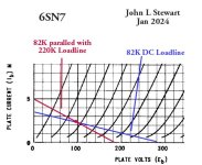
Here are the OPs loadlines on the 6SN7 on page One. Notice the available voltage swing is reduced a lot.
And the shorter distance between the grid lines to the right of the 2.7V bias is a source of
even order harmonics............ie 2H, 4H, 6H.....Etc🙂
And the shorter distance between the grid lines to the right of the 2.7V bias is a source of
even order harmonics............ie 2H, 4H, 6H.....Etc🙂
Attachments
Here are the OPs loadlines on the 6SN7 on page One. Notice the available voltage swing is reduced a lot.
Ok, now "dumb that down" for me to understand. And then fix it, LOL. 😀
Its time you pulled out those text books you mentioned some time ago, you had studied electronics a while back.Ok, now "dumb that down" for me to understand. And then fix it, LOL. 😀
You seem to think you will get all you need to know here with little or no sweat on your part.👎
Many of us studied for years & than practiced at the profession, it wasn't easy.
So get your a$$ in gear & show us you are serious.🙄
Its time you pulled out those text books you mentioned some time ago, you had studied electronics a while back.
You seem to think you will get all you need to know here with little or no sweat on your part.👎
Many of us studied for years & than practiced at the profession, it wasn't easy.
So get your a$$ in gear & show us you are serious.🙄
You missed the part where I almost failed basic college physics over 30 years ago (the text books you reference) and had to hire a tutor twice per week to get through it. Sorry, I'm not as smart as some of you, especially with math, and there is insufficient time remaining in my lifetime to gather anything even close to everyone's experience. Therefore, I rely on the kindness and generosity of anyone willing to mentor and tutor as I learn. Doing it online also helps countless others both now and in the future as the threads remain here for reference. I think I mentioned that the purpose of this kit is learning. So what have I learned recently? Let's have a look.
- Last week, with the one-on-one, private help of a nice member, I did draw my first load line and figured out what it meant, sort-of. That was the first time I had ever tried to figure out a load line or considered what one meant or how or why we draw them. Someone here earlier pointed out an online load line calculator, and I did try it last week. It requires a whole lot of variables, and I don't yet understand all of them.
- Then there is the issue of the effects of paralleling the two triodes inside a 6SN7, so I had to go read the parallel operation thread I referenced earlier by @6A3sUMMER which I am still digesting.
- Last week I finally got some understanding of how we get from an output transformer that sags badly at both ends, to something at the output that doesn't sag so much. That required the help of others here too, in another thread about transformers.
- Before this kit, I hadn't ever looked at a tube rectifier and had no idea how one worked. So I did that a few weeks ago, again with the help of members and I simulated it in PSUdesigner. Wow, that's a lot of voltage loss.
- Until I bought this kit, I didn't have any idea how a single-ended amplifier worked.
- This is the first time I have ever looked at a driver stage of any type.
- Until last week I had no idea what SRPP was. So I had to go learn a few things about that.
I give up. I'll save the stainless chassis, choke, tubes, and power transformer. Maybe I'll use them at some point in the future or give them to someone who will. I learned a lot, but I admit defeat.
I think you were heading for disappointment. It was looking like a lot of expense for a few watts when you are not experienced at designing your own tube amps.
It's never a good idea to rely totally on forums due to the myriad of opinions.
I would also agree that Tubelab.com have several tried and tested designs and I almost built one of theirs.
Then I spent a forune on iron to build a 30watt PP amp but I was fearful of the lethality of 500v HT, having no one at home to administer CPR so that was abandoned.
Instead I bought the ready assembled SE amp as a starting point. (I also hate metal working)
You got the hardware, you learned some new stuff. Why not build one of the variants discussed here and listen to it? You may be pleasantly surprised by the result.I give up. I'll save the stainless chassis, choke, tubes, and power transformer. Maybe I'll use them at some point in the future or give them to someone who will. I learned a lot, but I admit defeat.
It was looking like a lot of expense for a few watts when you are not experienced at designing your own tube amps.
It's never a good idea to rely totally on forums due to the myriad of opinions.
The extra expense needed at this point is almost irrelevant if I had some sort of reasonable expectation of success, and in pentode mode, I think I could live with the wattage. UL doesn't interest me and we need not go into why again, and neither does triode interest me. The real problem and the root cause of failure is that I wanted to try to learn enough to redesign the kit, and I'm too far down the learning curve to make that happen. Maybe some day.
Why not build one of the variants discussed here and listen to it?
It's just not worth it at this point. I bit off more than I can chew. If I come across a single-ended pentode EL34 schematic that will work and I think I can tackle it, maybe I'll try that one day. This kit is a single-ended pentode, but apparently it just doesn't work and I can't fix it.
Last edited:
?? stephe is showcasing a perfectly stable and robust design on her Skunkie Designs YouTube channel, SE EL34s, triode drivers, right now. Output valves G2s could be connected full pentode, partial ("UL"), or triode, with no other changes, and driving triodes could be octal (6SL7) with no other changes, or even 6SN7 with minor adjustments to cathode and anode load resistors. No drama.
Please don't let "The Best" (whatever that means) be the enemy of the Good. And, you already know a lot more about valve audio amplifiers than most folk on most forums IME.
All good fortune,
Chris
Please don't let "The Best" (whatever that means) be the enemy of the Good. And, you already know a lot more about valve audio amplifiers than most folk on most forums IME.
All good fortune,
Chris
- Home
- Amplifiers
- Tubes / Valves
- 6SN7 + EL34 SE stereo amplifier build - questions