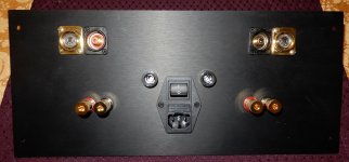
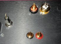
Made some progress last night and today. The power supplies are wired up and working properly - I'm getting 45V unloaded each side. Today I machined the screw holes for the aluminum front panel handles, and two small holes for the indicator light pipes (or LEDs if that becomes too fussy).
I also machined holes in the rear panel for two extra fuse holders since this is dual mono, and two holes for XLR jacks adjacent to the RCA jacks. Tomorrow I hope to fully assemble and wire the amp, set the AC gain, etc.
Nice, large, machined aluminum feet for the amp should be here in a couple of weeks or less.
I'm getting anxious to listen to this baby!
Oops - distracted typo above. NOT 45VDC unloaded - 27.75VDC both sides.
I really need to stop posting in a hurry when distracted with other things. At least I was focused on powering/testing/measuring 🙂
I really need to stop posting in a hurry when distracted with other things. At least I was focused on powering/testing/measuring 🙂
@Peppe: Thank you! I copied the input XLR gender on our Yamaha amp, and for some reason it has male jacks. 🤔 I now see our Sony TAN-80ES has female jacks. With the Yamaha, I use RCA adapters, and only use the RCA jacks on the Sony, so didn't think about the XLR cable gender. As I build more balanced gear like ZM's Iron Pre, my goal is to increase the overall connectivity.
I haven't wired them up yet, so it will be a quick easy swap. You've saved me time, thank you!
I haven't wired them up yet, so it will be a quick easy swap. You've saved me time, thank you!
Is it an integrated? Are they pre-outs?I copied the input XLR gender on our Yamaha amp, and for some reason it has male jacks. 🤔
Without a model number it's hard to tell.
No, it's a PC2002M amplifier. I just pulled it away from the wall to check, and it actually has both male and female. It's a professional series amp, so it has daisy chain inputs for connecting multiple amps. As I now recall, when I set up the amp I just used the RCA adapters I had handy at the time. Thanks!
Aaaaaaah! NICE amp. That explains it.No, it's a PC2002M amplifier. I just pulled it away from the wall to check, and it actually has both male and female. It's a professional series amp, so it has daisy chain inputs for connecting multiple amps.
Thanks, and yes, it really is a nice amp. A bit heavy and unwieldly in its position, so being lazy and pulling the adapter wasn't the best approach in this case!
Glad I could do it.You've saved me time, thank you!
When in doubt I just google Pass Labs rear panel

Initial function testing on the left channel shows excessive current draw and DC offset. Hooked up to my variable AC iso transformer and current meter, AC current draw at only 40VAC was about 1A. Using my DMM across one source resistor first, current draw rose to over 500mV on that resistor at about 50VAC. I then used my clamp on DC milliameter, and 60VAC resulted in 1800mA of current in either rail.
The bias current adjustment had very little effect - I could definitely not reduce it to a safe level. Also, confirmed all trimmers are in proper locations, e.g. 50k in P3, etc.
Offset was quite high at lower voltages - about 900mV, but was reduced to about 220mV as I bumped supply up to 50VAC, but I didn't take it further.
I shorted the inputs for testing. Also, thermal camera readings on the board while testing show source resistors reached about 36C, with output transistors at about 30C. No one part seemed overly hot, particularly the outputs. I have verified that the output transistors are not shorted to heat sinks.
Nothing looks amiss - no burned parts, etc., but I'll disconnect the L channel and do yet another close visual inspection, and probe with the DMM.
Last edited:
I pulled both boards from their heat sinks to inspect solder joints - thank you, Randy and Jim for the extra sets of critical eyes and useful suggestions last evening! 🙂 Nothing jumped out at any of us, but Randy noticed some solder joints that would benefit from more solder and better flowing, so I did that. At the same time, I checked all diodes (good), and with a good light and visors, checked for shorts and opens, and as Jim suggested (hey, it happens), verified that all components were stuffed in their proper locations.
I also pulled the trimmers to re-set their values, since I tweaked them while testing the left channel.
Today I will first check the right channel before moving back to the left. To make testing easier, I made up some longer power supply wires so I can lay the heat sinks down. Not many components in these boards, so the problem is likely to be something silly.
^ I am not sure re: the math that's involved... and this may be completely irrelevant, but...
For every Aleph I have put together including the A60 from Randy's boards, when using a Variac to ramp up the voltage, the initial current RISES RAPIDLY through the source resistors used to set bias. Then it falls after a certain voltage has been reached.
Without a complete understanding of the circuit... I can't explain why. If I get a few minutes, I'll toss a Variac on my build along with a DMM across the "bias" resistors and show you what I mean.
Again... this may not be AT ALL what you're experiencing, but I can demonstrate what I mean, and you can see if your experience is similar.
If your experience is similar, then perhaps all you need to do is ... crank 'er on up.
However, I would NOT do that until far wiser minds have weighed in. I'll try to get a link up later to a video or just try to capture it with a few pictures.
Thanks for weighing in, @ItsAllInMyHead. Since I chickened out when voltage across one of the source resistors went above 500mV, it may well be the case that AC (and therefore rail voltage) was just too low. Certainly, the offset went way down as I went from 40VAC to 50VAC. Also encouraging was that none of the outputs or source resistors was hotter than the others.
That would be awesome and appreciated if you document your voltages - thanks! In the meantime, I'll test the right channel - it will be interesting if I see the same behavior as the left - could mean it just needs turning up, or that I made the same stuffing error in both boards and need to re-check. I have a process when stuffing parts - the bag stays in front of me until all parts are stuffed and verified, then the next part goes in. Having 2 boards is always a great QC. Still, I've learned never to claim infallibility. 🙂
That would be awesome and appreciated if you document your voltages - thanks! In the meantime, I'll test the right channel - it will be interesting if I see the same behavior as the left - could mean it just needs turning up, or that I made the same stuffing error in both boards and need to re-check. I have a process when stuffing parts - the bag stays in front of me until all parts are stuffed and verified, then the next part goes in. Having 2 boards is always a great QC. Still, I've learned never to claim infallibility. 🙂
I would increase the voltage on the variac so that you see say 300mv across the source resistors. Then measure the voltage drop of the source resistors one by one to see if the voltage is exceedingly high on any particular mosfet. You can also do an ohm check from the center pin to the ground (mosfet screw head) to check to make sure the insulators are insulating properly.
Hi @Mikerodrig27 - thank you. One of the first things I did was a check of the Mosfets - all good, no shorts to case. All insulators are good, as well.
Since I well exceeded 300mV across the source resistors, I bailed out at 50VAC input. I'm going to use my DBT instead this time and monitor the light and ammeter, rather than do a hard control of V with the variac. Should get to that within the hour, and report findings. Thanks!
Since I well exceeded 300mV across the source resistors, I bailed out at 50VAC input. I'm going to use my DBT instead this time and monitor the light and ammeter, rather than do a hard control of V with the variac. Should get to that within the hour, and report findings. Thanks!
- Home
- Amplifiers
- Pass Labs
- Classic Aleph Amplifier for Modern UMS Chassis Builder's Thread

