I really like that explanation… I will try to grasp further when feet are back on terra firma.
As always, thank you for helping the dodos!
Zoom…
As always, thank you for helping the dodos!
Zoom…
Agreed... So ignore term... I explained what the % meant. It's just the % of two measurements. Forget the word gain etc.looking at graph you posted (#953), for me is puzzling that violet trace (lowest THD while furthest with power on 4R) is with smallest Aleph CCS AC gain
Agreed... that's why I shouldn't have used that term on the graph. I should have titled it...while, for my peanut brain, it should be for highest Aleph CCS AC gain
"% of voltage across resistor with jumper cap in place"
I never worried too much about it... with that said... I thought that there was in some manner of speaking current to be 'gained' also vs. just a percent contribution. I'll always share my dodo thoughts...again, how I'm grasping Pa's nomenclature:
if output current swing is 1A, contribution of lower amp half is 0.5A and contribution of upper amp half is 0.5A, that means that Aleph CCS (upper half) AC gain is 50%
if output current swing is 1A, contribution of lower amp half is 0.35A and contribution of upper amp half is 0.65A, that means that Aleph CCS (upper half) AC gain is 65%
if output current swing is 1A, contribution of lower amp half is 0.65A and contribution of upper amp half is 0.35A, that means that Aleph CCS (upper half) AC gain is 35%
simple as that
I thought... that.... if we had some made up Iq, call it 1A for the output devices, that turning the knob and increasing the 'current gain' would allow some extra % of current at the output as the amp moved more toward push-pull from SE and the current source devices started kicking in some (or more of a) contribution. I know we're saying sort of the same thing, and the measurements are what they are... but the important thing (to me) is that there is in-fact more output current available to the speakers at some settings vs. others. It's not just ratio (I think) ... It's mainly that you get more current... which is nice for lower impedance loads.
Example with made up number. I'm not sure if this can be done, but when I get back, I'll run the pots to their extremes and see what turns up. I'll also show the clipping points.
1A Iq (measured as sum of output devices, but not including current source devices)
If amp clips at 1A of current output (let's call it SE) then current gain would be 0%.
Also the way you do the math the ratio... 0% from CCS.
If someone twiddles some knob...
Amp now clips at 1A5.
We get 500mA more... so 50% current gain.
The way you do the math, the contribution would be 500mV / 1500mV => 33%
To me... the numbers as mentioned are not terribly important. What is important is that if people want that magic 100W (not me ... ) that they now know how to do it using Randy's guide. If they didn't already.
I really like your explanation though.
With that said, it was super fun running a quick and dirty test to show that yes, Virginia, there is a Santa Claus we affectionately call Papa. He brings lovely gifts that will provide 100W into 4R loads at 1%. He has an incredible elf that created boards and an even better build guide so that dodos like me can have an amplifier of their dreams.
Agreed...what is slightly confusing, as term - without really grasping entire Papa's procedure is that "gain" is used instead of "contribution", with number expressed either as percentage or as something lower than 1, where 1 as one whole is sum current output of amp
As mentioned above - When I get back, I'll rerun everything just to be sure, and I'll also use your two DMM trick and show the clipping points into 4R. It'll be fun. Per usual if you want to see any other fun stuff, just shoot me a note.


Here's a quick summary ...
I likely missed inputting 8R for the 'purple' in #953. That seems most likely. I told the computer it was a 4R measurement, when in-fact, it was likely an 8R load. I was in a rush. My apologies.
I was not able to replicate a that beautifully sloped graph showing 100W at 1% with 4R load. However, when I intentionally fat finger the result, you can see that shows the increase in power output. See the graph below with the appropriately labeled trace.
That's not to say that the 'current gain' doesn't affect power output at 4R. You can do some really, really, really funky things with it. With that said... in order to reduce (hopefully) confusion, here's a simple graph showing a few replicates done quite some time apart to help ensure repeatability and lack of fat fingers affecting posted results.
I'd love to see others' results and even better would be a test of a factory Aleph 60. If someone wants to send me one to test... 🙂
Also, here is a summary of various ways someone might run some math for calculating the setting. First is the way described in Randy's guide. The % is for illustration only, it is not meant to imply % current gain. It's just the % of the initial value.
This shows the contribution from each set of devices to the total. Jumper on.
What I'd encourage is that if anyone doesn't have a way to check distortion that they simply do it exactly as Randy described in the manual and leave it alone. If you do have a way to measure ... you can have some serious fun, and create some really funky results / performance. You might even be able to eke out a tiny bit "better" performance... at least on paper. The critical thing is to run the checks at outputs and loads that matter TO YOU. I have little concern for anything past about 10W, and I'm going to adjust my build to suit my tastes/needs/desire for a tad less heat. This was just for fun.
The "Initial" Value below is noted in the first chart along with the rest of the measurements. As soon as you progress past 45% into the 40% area, you start to see a "knee". As you progress further, it gets progressively more pronounced. As you bring the things into the 0% (as measured by the way I indicated) range and beyond, things start to get seriously funkadelic.
tl;dr - Randy has provided a wonderful way to find a great setting without much risk. Twiddle further at your own risk for your own reasons.
Have fun!

I likely missed inputting 8R for the 'purple' in #953. That seems most likely. I told the computer it was a 4R measurement, when in-fact, it was likely an 8R load. I was in a rush. My apologies.
I was not able to replicate a that beautifully sloped graph showing 100W at 1% with 4R load. However, when I intentionally fat finger the result, you can see that shows the increase in power output. See the graph below with the appropriately labeled trace.
That's not to say that the 'current gain' doesn't affect power output at 4R. You can do some really, really, really funky things with it. With that said... in order to reduce (hopefully) confusion, here's a simple graph showing a few replicates done quite some time apart to help ensure repeatability and lack of fat fingers affecting posted results.
I'd love to see others' results and even better would be a test of a factory Aleph 60. If someone wants to send me one to test... 🙂
Also, here is a summary of various ways someone might run some math for calculating the setting. First is the way described in Randy's guide. The % is for illustration only, it is not meant to imply % current gain. It's just the % of the initial value.
| Output FET Only | |||
| Setting | Jumper Off (mV) | Jumper On (mV) | % of Jumper on Value to Jumper off Value |
| Initial | 200 | 120 | 60% |
| 1 | 200 | 100 | 50% |
| 2 | 200 | 90 | 45% |
| 3 | 200 | 80 | 40% |
| 4 | 200 | 70 | 35% |
| Output FET (mV) | CS FET (mV) | % of Output FET to total | % CS FET to total |
| 120 | 85 | 59% | 41% |
| 100 | 105 | 49% | 51% |
| 90 | 115 | 44% | 56% |
| 80 | 125 | 39% | 61% |
| 70 | 135 | 34% | 66% |
What I'd encourage is that if anyone doesn't have a way to check distortion that they simply do it exactly as Randy described in the manual and leave it alone. If you do have a way to measure ... you can have some serious fun, and create some really funky results / performance. You might even be able to eke out a tiny bit "better" performance... at least on paper. The critical thing is to run the checks at outputs and loads that matter TO YOU. I have little concern for anything past about 10W, and I'm going to adjust my build to suit my tastes/needs/desire for a tad less heat. This was just for fun.
The "Initial" Value below is noted in the first chart along with the rest of the measurements. As soon as you progress past 45% into the 40% area, you start to see a "knee". As you progress further, it gets progressively more pronounced. As you bring the things into the 0% (as measured by the way I indicated) range and beyond, things start to get seriously funkadelic.
tl;dr - Randy has provided a wonderful way to find a great setting without much risk. Twiddle further at your own risk for your own reasons.
Have fun!

It’s all the same boards… just how many you want to string together.
I’m sure @rhthatcher has boards. A fantastic project.
😃
I’m sure @rhthatcher has boards. A fantastic project.
😃
I have too many amps in my small living room. Thats why i need to sell my big bad Aleph 30+. Located in northern Germany, collection preferred..
click here for my diyAudio marketplace ad
Check out more details about this build
€100,- of the sales price will go to @rhthatcher because he donated the boards and semis
click here for my diyAudio marketplace ad
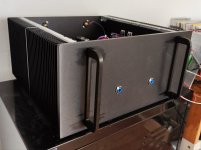
- 230V build!
- optimised for current-hungry 4-ohm loads
- 2x 60W @ 4 ohm (resistive load)
- 2x 35W @ 8 ohm (resistive load)
- 5U 400 Modushop UMS enclosure
- dual mono PSU with two toroidy transformers
- individual power switches and soft start modules per channel
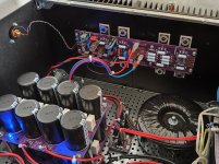
- CRCRC filter for each rail, instead of a shared CRC Filter
- local reservoir / decoupling capacitors on the new revision of the PCB
- Harris / Fairchild 9610s instead of Vishay in the old build
- 2 additional MOSFETS per channel, compared to Aleph 30
- source resistors and output resistors of 0.68 ohm instead of 0.47 ohm in the A30 build
- current limiter set to much higher value
- almost double the heat dissipation compared to standard A30
Check out more details about this build
€100,- of the sales price will go to @rhthatcher because he donated the boards and semis
Attachments
A good deal!
Mine will be almost a clone of your clone. May I just ask why you are using 0R68 for source and output resistors? I have plenty of 0R47 as in the original A30.
Mine will be almost a clone of your clone. May I just ask why you are using 0R68 for source and output resistors? I have plenty of 0R47 as in the original A30.
Thank you Addidub! I will pay that forward and make a Happy New Year raffle for a A30 PCB and mosfet kit. I’ve done fully built board raffle the past 2 years, but my current A30 boards are in daily use. So it’s going to be a kit this time.
@Peppe i did not properly document how i made this decision regarding the source resistors. For the output resistors i found this remark in my build docs:
I guess i have found this remark somewhere at diyaudio forum in a discussion about Aleph. Maybe you could find it if you try to search for fragments of the quote above.
Attached is a table i created to compare different Aleph iterations. Hope it helps..
@rhthatcher No need to thank me. Remember, you donated the boards and semis to me. I dont think this giant amp will sell fast. Maybe i should advertise it on my local craigslist as 350W electric heater?
Output Resistors value should be half the value of parallel sum of the source resistors of the current source
Source R: calculated to reach at least 0.4V DC through Source R - even with sagged linear Power Supply
Around 0.4V DC on Source R is needed to achieve proper current limiter circuit function
I guess i have found this remark somewhere at diyaudio forum in a discussion about Aleph. Maybe you could find it if you try to search for fragments of the quote above.
Attached is a table i created to compare different Aleph iterations. Hope it helps..
@rhthatcher No need to thank me. Remember, you donated the boards and semis to me. I dont think this giant amp will sell fast. Maybe i should advertise it on my local craigslist as 350W electric heater?
Attachments
@Peppe i did not properly document how i made this decision regarding the source resistors. For the output resistors i found this remark in my build docs:
I guess i have found this remark somewhere at diyaudio forum in a discussion about Aleph. Maybe you could find it if you try to search for fragments of the quote above.
Attached is a table i created to compare different Aleph iterations. Hope it helps..
@rhthatcher No need to thank me. Remember, you donated the boards and semis to me. I dont think this giant amp will sell fast. Maybe i should advertise it on my local craigslist as 350W electric heater?
To answer the question mark about the A5s..
The OEM A5 is a Borg Case stereo unit. 60/90 wpc into 8/4 ohms.
But as it would just happen, I have a pair of A5s that were done in the smaller Rawson cases, so they are mono.
Also, I believe both A5 turbo variations (V2 and V3) are mono blocks.
Nice. And the 400VA is just taller but not wider than the 300VA.
What about the snubber resistor?
What about the snubber resistor?
I did not properly document it how I found the values for the snubbers. I would suggest to use a Quasimodo bellringer by @Mark Johnson to figure it out with your actual donuts.
Well, better a little late to the party than miss it altogether. After getting lots of good input and suggestions from Randy and Jim (6L6) (THANKS, GUYS!), I bought boards and semis from Randy, a 4U/400 UMS chassis from Gianluca, parts for the boards, and Antek AS-3220 transformers for a dual mono, single-chassis Aleph 30.
Progress is being made in fits and starts - too many other projects and responsibilities getting in the way of hobbies, but after having to do a little extra work to get a mis-drilled heat sink to line up properly and completing the mockup, I'm about ready to start bolting up and wiring up the modules.


Progress is being made in fits and starts - too many other projects and responsibilities getting in the way of hobbies, but after having to do a little extra work to get a mis-drilled heat sink to line up properly and completing the mockup, I'm about ready to start bolting up and wiring up the modules.
Decided to add spacers beneath the perforated bottom panel where they bolt to the side rails - otherwise, tightening the screws and nuts would distort the rail and the bottom panel a bit.
Supply wires to boards now fitted. Used 12 ga. for speaker leads, 14 ga. for power to boards. Techflex just arrived, so transformers will go in next, but AC supply wiring will happen after more wire shows up.
I decided to install the cyan LEDs on the V8 PS boards, and run fiber optic light pipes to the front panel just to be tricky. Still have to mill holes in the front panel, but still debating whether I use 1 per channel or 2, in what configuration, and how spaced/placed in the front panel. I'm not installing a switch on the front - just the LEDs.
Any suggestions anyone?
- Home
- Amplifiers
- Pass Labs
- Classic Aleph Amplifier for Modern UMS Chassis Builder's Thread