Merlinb
Than the solution will be ; pentode at input as voltage gain stage DC coupled to grid of standard Concertina PI but powered from bipolar PSU ?
Than the solution will be ; pentode at input as voltage gain stage DC coupled to grid of standard Concertina PI but powered from bipolar PSU ?
The swing problem is not resolved even using 500V supply . A cathodyne can't give you 200Vpp swing , or more , for 6AS7 cathode biased .
And of course you can't push it to the max with high distortion , or what is this , a contest for stinginess ?
And of course you can't push it to the max with high distortion , or what is this , a contest for stinginess ?
Last edited:

jcalvarez
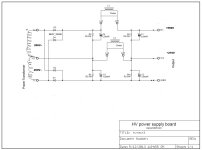
that may work good in combination with this type of PSU , where +275V will be supply line for 6AS7 PP-OPS , and +550V line to supply input and PI stage .
btw , I wonder what result will be if instead of that 6F12P tube we use 6SL7 (6H9C) tube ?
that may work good in combination with this type of PSU , where +275V will be supply line for 6AS7 PP-OPS , and +550V line to supply input and PI stage .
btw , I wonder what result will be if instead of that 6F12P tube we use 6SL7 (6H9C) tube ?
Attachments

As the output tube 12SN7 is amplifying the strain on the cathodyne and input tube is much lower , 600V is for 12SN7 ... completly different than using cathodyne directly for output
Last edited:
To be honest I still believe the LTP is the best option here. Are there other options? Sure, but the LTP is the simplest one, imho.
Same.To be honest I still believe the LTP is the best option here. Are there other options? Sure, but the LTP is the simplest one, imho.
I love the cathodyne and prefer it in every instance where I can use it- but this is not the place for it. Unless you go for a Williamson front end and follow up with higher voltage gain stages it doesn't make sense to use it here. 90% of my amps have used the cathodyne- and of the dozen or so finished push-pull amps on hand that I held onto- all use a cathodyne.
Personally, if this were my project that for whatever reason I was required to make happen- I would grab a filament transformer- run it backwards off of the filament supply, and stack that on the plate supply for the differential and front end. Another ~120-150 volts rectified of headroom will make a huge difference here.
Sorry not replied sooner, my PC died.
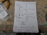
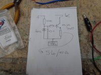
Re the CCS, I use the attached. I prefer using a MJE340 or BD139 with or without another transistor. The extra tranny gives a higher impedance but there's not much in it. I use Piher 500r presets with a fixed R for the emitter R and use 6V2 zeners. A 6V2 zener gives more adjustment than a LED. With a 6V2 zener Er is found by dividing 5.4 by what Ik you want. Remember for an LTP thats Ik x 2.
Hope that helps, Andy.
Think so, having trouble visualising that. A lot of amps use a tap off the secondary to power a bias supply, see - http://www.valvewizard.co.uk/bias.html I prefer a separate tfmr & bridge rectified supply, mainly because the negative V supply is ripple free & I get more Vout.could create a negative supply from?
Re the CCS, I use the attached. I prefer using a MJE340 or BD139 with or without another transistor. The extra tranny gives a higher impedance but there's not much in it. I use Piher 500r presets with a fixed R for the emitter R and use 6V2 zeners. A 6V2 zener gives more adjustment than a LED. With a 6V2 zener Er is found by dividing 5.4 by what Ik you want. Remember for an LTP thats Ik x 2.
Hope that helps, Andy.
Attachments
Not falling into the main body of the thread, but true to the thread title, sometimes the "best" design option is to accept that a mu of 2, not very linear, output valve is just not a good design choice. Engineering is evolution, mostly by death of the not-fit-est. Good information lives to procreate, both as continuing designs and as cautionary tales.
All good fortune,
Chris
All good fortune,
Chris
So does bad or incorrect information, EG $1000 power cables made from sudo copper, wood cased coupling capacitors to ensure a woody timbre & all that other audio foollery. If your relatively inexperienced sometimes a circuit or valve choice that gets the job done but may not be 100% optimum is all that's needed.Good information lives to procreate
Kushti bok, Andy.
Another option with split-load/cathodyne/concertina is placed it in the front as the input, acting like a 1:2 input transformer and not inside the feedback loop, and cap coupled the PP signal to your favorite PP or differential/LTP driver circuit.
My allegiance to split-load/cathodyne/concertina is that each of the two phases of PP goes through the same number of active devices. Unreasonable? Maybe...
My allegiance to split-load/cathodyne/concertina is that each of the two phases of PP goes through the same number of active devices. Unreasonable? Maybe...
Nothing beats the dn2540 fet in concertina setup. KSC3503 is next best.
I get 60v pp off both legs from 130v B+
Fed from 12AX7.
350v B+ would yield 170v pp per leg
I get 60v pp off both legs from 130v B+
Fed from 12AX7.
350v B+ would yield 170v pp per leg
Last edited:
I'm going to breadboard a power supply and one channel so I can play around with various configurations.
The power stage will remain fixed as 6AS7, however I might have to change to bias resistors if the B+ voltage varied a lot. I have octal relay bases which are superb for breadboarding (see attached). There's not a noval valve base relay socket unfortunately, however I'll sort something out.
Breadboarding will allow me to easily change components and configuration of the phase splitter/inverter type. I will buy some DC voltage display meters to wire in so I can easily take notes of the circuit voltage levels.
I've got a digital scope knocking around somewhere so maybe time to dig that out or possibly invest in something newer...
Oh, I've taken delivery of a number of ECF82 valves NOS so I will experiment and compare in LTP with CCS against 6N1P, with CCS. And a measure of negative bias as well.
Attachments
- Home
- Amplifiers
- Tubes / Valves
- HiFi phase splitter - "best" design option?