After reading the thread, here are a few thoughts for a newcomer to amp electronics...
I have a number of multimeters, including the exact same one you have here. And, within its range limits, it's fine. It might not be as accurate as a better one, but it should be easily accurate enough - but not for low-value components like emitter resistors.
When using a light bulb as current limiter, you need to know what to expect from it. If an amp is good, the bulb should light up fairly brightly just briefly (as the power supply capacitors are charged), and then dim. But if the bulb stays bright, switch off! It means you have a dead short in there somewhere.
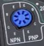
There's one piece of test kit I'd strongly recommend to any newcomer, a cheap Chinese-made component tester - I'll add a photo of one below. It should cost around €20. I use mine all the time, probably even more than my multimeter. The real beauty is that you don't need to know what a component is, which way round the pins go, whether a transistor is NPN or PNP - the tester will tell you all of that. For accurate measurements, no - but for a quick check of a component, it's a real time saver.
Good luck.

I have a number of multimeters, including the exact same one you have here. And, within its range limits, it's fine. It might not be as accurate as a better one, but it should be easily accurate enough - but not for low-value components like emitter resistors.
When using a light bulb as current limiter, you need to know what to expect from it. If an amp is good, the bulb should light up fairly brightly just briefly (as the power supply capacitors are charged), and then dim. But if the bulb stays bright, switch off! It means you have a dead short in there somewhere.
There's one piece of test kit I'd strongly recommend to any newcomer, a cheap Chinese-made component tester - I'll add a photo of one below. It should cost around €20. I use mine all the time, probably even more than my multimeter. The real beauty is that you don't need to know what a component is, which way round the pins go, whether a transistor is NPN or PNP - the tester will tell you all of that. For accurate measurements, no - but for a quick check of a component, it's a real time saver.
Good luck.

Draw a schematic, which has been done as good as possible. Unfortunately OP can't read schematics.
Hugo
Hugo
wow this is a cool thing not jsut for this but for any component because i fix stuff al the time mostly minor stuff but with this i can do more 😀
Same as a number of people have suggested - draw a schematic, as I'm largely lost without one.After two weeks and 180 posts I want to ask you guys one thing, if it were you, what would be the first thing you would do to diagnose this amp?
can someone draw it if i provide resistor values and also for capacitors and other components ? i can do that but i dont know how to draw schematics
https://www.diyaudio.com/community/...ing-after-shorting-output.406712/post-7538570Same as a number of people have suggested - draw a schematic, as I'm largely lost without one.
With more pictures in a few posts I guess it would be doable by now to draw a correct one.
Hugo
i will use one of my pictures that i have and type all resistor values there and capacitors and for transistors i will check them later as i said with tester on my multimeter
Thinking a bit more, with so few components here, I might just go for a brute force approach first.https://www.diyaudio.com/community/...ing-after-shorting-output.406712/post-7538570
With more pictures in a few posts I guess it would be doable by now to draw a correct one.
Hugo
Remove and test the semiconductors, then do the same with the passive components.
I'd probably replace any electrolytics where I happen to have suitable ones (I always over-order when I buy, and I save old ones that still measure well, so I have a good variety), as they can appear OK at test meter voltages but not work properly at full voltage (same goes for other components really, but I've seen it more often with old electrolytics - and I'd repace them all after fixing it anyway).
With a bit of luck, I'll find the bad components and can replace them. Not guaranteed, though, as some things can measure fine at test voltages but still fail at full voltage.
Next, a dim build check. If that looks OK with no bulb brightness, let it run for 10 minutes or so.
Then, try at full voltage, checking carefully to see if anything gets hot where it shouldn't (if that would mean touching metal parts, one of my meters will measure temperature, so I'd use that).
If there's no sign of disaster, connect it up and try it.
If it still doesn't work, check that voltages look right in various places. If voltages look OK, use an oscilloscope to do some signal tracing. These steps need the schematic plus the ability to understand it.
If I can't find what's wrong after all that, accept defeat and give up.
Here's a thought...
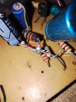
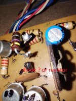
What's that I've marked in the photo below? It looks like three resistors in series (which is fair enough to make up the desired resistance). But the top one looks like it might be blackened, I can't see anything much of the bottom one, and the middle one looks like it might be cracked between the violet and silver bands?
I'd definitely test those.
Hi sg97,
Normally you would measure from base to emitter, then base to collector to do a rough check and identify the terminals. The base is the one that gives you a diode reading to the two other terminals. Once you figure that out, you can tell whether you have a PNP or NPN transistor or sometimes a shorted one. THen you measure from collector to emitter to make sure that isn't shorted.
You'll get the hang of it. That is why I suggested you practice with known good transistors first. Once you know what to expect, you'll find this much easier.
A diode junction will give about a 0.45 VDC to 0.65 VDC drop for silicon transistors, a Germanium will drop 0.2 VDC to 0.4 VDC as a rule with most diode check functions. A Darlington (silicon) transistor will drop 0.7 to 0.9 VDC across the base to emitter junction, the base to collector will be the same as the others.
So please, take some time with known, good transistors. You do not need the same part numbers to replace them, if you find bad ones let us know the number and we can find a substitute for you. Many original part numbers are bad, even when new. I refuse to buy parts from anywhere but authorized distributors selling current parts. There is nothing worse than getting a bad new part and assuming it is both good, and compatible with the circuit.
-Chris
Hi sg97,
Remove and change as little as possible. Do not introduce variables at this point please.
Take lots of pictures as you work, you will thank me later.
Remove and change as little as possible. Do not introduce variables at this point please.
Take lots of pictures as you work, you will thank me later.
i te
Here's a thought...
What's that I've marked in the photo below? It looks like three resistors in series (which is fair enough to make up the desired resistance). But the top one looks like it might be blackened, I can't see anything much of the bottom one, and the middle one looks like it might be cracked between the violet and silver bands?
I'd definitely test thos
i think its like 47 ohm if i remember i did measure that before and also all the resistors thes are ok only ones with wire dont workHere's a thought...
What's that I've marked in the photo below? It looks like three resistors in series (which is fair enough to make up the desired resistance). But the top one looks like it might be blackened, I can't see anything much of the bottom one, and the middle one looks like it might be cracked between the violet and silver bands?
I'd definitely test those.
View attachment 1254452
No. The big ones need lots of current to work properly, the tester cannot provide this.btw can i use this tester to test big ones ?
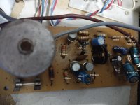
First picture 1k is correct. 2k should be 2.2k but that's OK.
The one you can't measure should read 33k
The one with the lifted leg is 5.6k.
Second picture 220ohm is OK
330ohm is OK
2.2k is OK
5.6k is OK
All others are hard to tell for I can't see the colours.
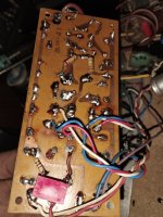
Third picture. You need to lift one leg to measure both.
The left one shoud read 210k and the right one 120k.
You need to lift the ones with a coil around and take one side of the coils off.
Also, the one that measures 132k needs a closer look. Lift one leg and measure.
What's beneath them?
Hugo
The one you can't measure should read 33k
The one with the lifted leg is 5.6k.
Second picture 220ohm is OK
330ohm is OK
2.2k is OK
5.6k is OK
All others are hard to tell for I can't see the colours.
Third picture. You need to lift one leg to measure both.
The left one shoud read 210k and the right one 120k.
You need to lift the ones with a coil around and take one side of the coils off.
Also, the one that measures 132k needs a closer look. Lift one leg and measure.
What's beneath them?
But it can be measured with the diode tester to look for shorts. I would think that suffices for now. 🙂No. The big ones need lots of current to work properly, the tester cannot provide this.
Hugo

If there are no shorts, you can then test them using a 9v battery, a 10k resistor and a 100 ohm resistor. Connect the 10k to base, and the 100 ohm to collector. Connect the other ends of both resistors to battery+. connect emitter to battery- . If nothing starts to smoke or get too hot (the 100 ohm resistor might get pretty warm) measure the voltage across each resistor. With ohms law you can then calculate the current through each resistor. The ratio between the two is the gain of the transistor.But it can be measured with the diode tester to look for shorts.
- Home
- Amplifiers
- Solid State
- transistor amp not working after shorting output