I can't seem to PM you as my account too new.Ya a few, shoot me a PM
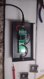
Thank you Mark Johnson. You inspired me to try having PCBs produced from your Gerber's. Had 5 boards made. All 5 stuffed, only missing current sensing resistors for 3 of the boards.
Bought some cheap aluminum project boxes off Amazon, trying the 2 units in series like posted previously in this thread. Not sure I can hear the difference but they where fun making them.
Bought some cheap aluminum project boxes off Amazon, trying the 2 units in series like posted previously in this thread. Not sure I can hear the difference but they where fun making them.
Attachments

Nicely done!Thank you Mark Johnson. You inspired me to try having PCBs produced from your Gerber's. Had 5 boards made. All 5 stuffed, only missing current sensing resistors for 3 of the boards.
Bought some cheap aluminum project boxes off Amazon, trying the 2 units in series like posted previously in this thread. Not sure I can hear the difference but they where fun making them.
--Tom
Builders and users of PO89ZB may enjoy taking a look at the SMD spinoff called AmyAlice .
I need a little help, I found this:
https://www.mouser.it/ProductDetail/605-RMCJ1U00R04FS
Is this a good choice for this project?
Thank you in advance an sorry for the noob question!
Have a nice day
Sergio
https://www.mouser.it/ProductDetail/605-RMCJ1U00R04FS
Is this a good choice for this project?
Thank you in advance an sorry for the noob question!
Have a nice day
Sergio
The two datasheets look approximately identical, even the formatting. It is a great substitution! Congratulations on discovering it.
Sergio and Mark - My apologies. I made an error in my parts list. I had 22mm lead spacing noted vs. the correct 12. Thanks to you both, now my parts list is (more) correct.
thank you so much for the confirmation, when I look for alternatives I always have a lot of insecurities.
Now I can place the order in complete safety.
Thanks again
Now I can place the order in complete safety.
Thanks again
That looks like the correct one to me but note that its End of Life (EOL), which is something you'll find to be common with many of the few options for current-sense resistors (CSRs). The data sheets for these have all the key information you need: lead spacing, dimensions (height/width), resistance value as well as power handling. Note de-rating specifications as you might be able to find a smaller power handling that actually still handles the specified amount. I haven't found any that were worse than %5 rated, but it costs next to nothing to get %1. I think the ones I used in the last run of kits were %.05 in fact, and they cost a penny more than the %1 values. They're really just laser-cut pieces of sheet metal after all! 🙂I need a little help, I found this:
https://www.mouser.it/ProductDetail/605-RMCJ1U00R04FS
Is this a good choice for this project?
Thank you in advance an sorry for the noob question!
Have a nice day
Sergio
As to which to select - you need to choose CSRs with values in the .05-.04R range and mind the power rating as per @Mark Johnson 's design that is spelled out in the top post in this thread (1W min), to ensure you won't let the smoke out. Note that the next jump in CSRs Ive found is 3W and I've not found any that will physically fit on the board because that power handling is just physically bigger.
Happy noise-free listening!
--Tom
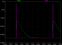
RE: "not sure I can hear the difference" - have you tried measuring the output with and without the filter? There is a lot of information in this thread about how to arrive at some very precise measurements. If you are queezy about those details, feel free to DM me and I can show you. Even the "non-super precise" approach will demonstrate that the filter is working and really only needs a DVM and some input source if you don't have a signal generator. A warning though: once you hear what the filter is eliminating, you'll never be able to un-hear it. You've been warned. 😊🤓Thank you Mark Johnson. You inspired me to try having PCBs produced from your Gerber's. Had 5 boards made. All 5 stuffed, only missing current sensing resistors for 3 of the boards.
Bought some cheap aluminum project boxes off Amazon, trying the 2 units in series like posted previously in this thread. Not sure I can hear the difference but they where fun making them.
--Tom
Hello Mark. I have extra positive experiences with the PO89ZB, for powering the DAC.
Is it possible to make the same filter but for a load of 5 A. After the Mean Well power supply LRS-200-36.
Regards!
Asim
Is it possible to make the same filter but for a load of 5 A. After the Mean Well power supply LRS-200-36.
Regards!
Asim
Let's pretend that post #1094 said, "To all members of diyAudio Forum and readers of the PO89ZB thread, I would like to ask a question please, and I will be grateful for any and every reply. Thank you!"
Would anyone like to offer an opinion or suggestion about the question asked? Perhaps the words "series" and "parallel" stimulate your creativity?
Would anyone like to offer an opinion or suggestion about the question asked? Perhaps the words "series" and "parallel" stimulate your creativity?
I suggested him the other day on a local DIY forum to connect three of your filters in parallel, there are two series resistors 0,04ohm inside and 0,1ohm in the coil, so it will be a good current distribution. If this is not enough, additional balancing resistors can be added in front of (or behind) each filter. Although I'm not sure if there are any undesirable effects with a parallel connection and additional resistance.
In addition, the specified 5A is not enough for the TPA3255 amplifier powered by 36VDC, it needs at least twice as much. It is a powerful device even if it is miniature (2x90W at 8 ohms, 2x170W at 4 ohms).
In addition, the specified 5A is not enough for the TPA3255 amplifier powered by 36VDC, it needs at least twice as much. It is a powerful device even if it is miniature (2x90W at 8 ohms, 2x170W at 4 ohms).
Last edited:
Hi Asim,Hello Mark. I have extra positive experiences with the PO89ZB, for powering the DAC.
Is it possible to make the same filter but for a load of 5 A. After the Mean Well power supply LRS-200-36.
Regards!
Asim
Is that a peak or continuous 5A/36V load?
Depending on your application (assuming an amplifier?), you might take a look at Mark Johnson's "Tuba" filter/regulator.
https://www.diyaudio.com/community/...is-incl-thump-kill.379747/page-9#post-7358641
Already well utilized by some number of happy VFet owners. 🙂
I built some of these for some years agoe and tried them around but never heard any difference but today I tried one
beacause I had some whining sound from my new DAC and it lowered it remarkabel!
I don't say it all disappeared but it payed of this board now. 🙂
Thanks!
And Merry Christmas!
beacause I had some whining sound from my new DAC and it lowered it remarkabel!
I don't say it all disappeared but it payed of this board now. 🙂
Thanks!
And Merry Christmas!
- Home
- Source & Line
- Analog Line Level
- PO89ZB, an inline DC filter for SMPS wall warts. Preamps, HPA, Korg NuTube, etc