There are plenty or good examples of working amps with and without grid stopper resistors here, and elsewhere. The thing that has not come up here yet is the Gm of the tube in question. Grid stoppers can often be omitted on a tube with low Gm. Show me a working amp without a stopper on the grid of a tube with a Gm of 15,000 or more.
Show me how to make one of those beam triode regulator tubes like the 6HV5A unconditionally stable without resistors, chokes and RF bypass caps with near zero lead length on nearly every pin. With a Gm of 65000 and a Mu of 300 those things are secretly oscillating while sleeping in their cardboard boxes. Just pop one of them into your favorite circuit, and SURPRISE! After spending a lot of time with those things, I gave up, twice. Other than in a follower configuration they just take off at some frequency between DC and about 40 MHz. Even if it's undetectable with test equipment, if the quiescent current in a circuit changes as you move your hands or a piece of metal over the design, without touching it, the design is oscillating. Sometimes the oscillation will stop when a scope probe touches the circuit. Often connecting resistors, caps or a bent coat hanger into that circuit at that point will NOT stop the oscillation. It's secretly laughing at you!
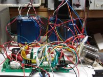
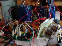
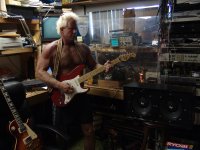
In a really DUMM, but surprising one hour experiment, I took a working Tubelab SSE board, removed the driver (12AT7) and output (6V6GT) tubes and wired in a compactron triode - pentode tube (6LR8) with cheap Radio Shack clip leads. This should have been a full on TV and radio jammer when powered up, but much to my surprise it not only worked, it worked good. I used the RF spectrum analyzer "sniffer," an OTA TV set, and an AM radio tuned to a weak station, all in proximity of the "furball" during testing and never detected any hint of oscillation as I messed with the amp while it was operational, tweaking component values, again with clip leads.
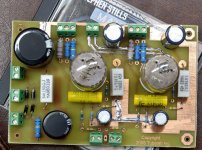
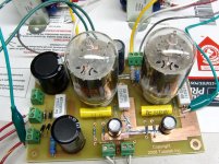
Once operational, listened to it for a while, then powered off and traced out a schematic for what I had created and laid out a PC board for it. It also worked on the first power up. This messy "furball" of wires rivals some of the thumbtack and tube sockets screwed to a pine board projects I made as a kid. I don't think it's possible to make a messier amp design.
Show me how to make one of those beam triode regulator tubes like the 6HV5A unconditionally stable without resistors, chokes and RF bypass caps with near zero lead length on nearly every pin. With a Gm of 65000 and a Mu of 300 those things are secretly oscillating while sleeping in their cardboard boxes. Just pop one of them into your favorite circuit, and SURPRISE! After spending a lot of time with those things, I gave up, twice. Other than in a follower configuration they just take off at some frequency between DC and about 40 MHz. Even if it's undetectable with test equipment, if the quiescent current in a circuit changes as you move your hands or a piece of metal over the design, without touching it, the design is oscillating. Sometimes the oscillation will stop when a scope probe touches the circuit. Often connecting resistors, caps or a bent coat hanger into that circuit at that point will NOT stop the oscillation. It's secretly laughing at you!
In a really DUMM, but surprising one hour experiment, I took a working Tubelab SSE board, removed the driver (12AT7) and output (6V6GT) tubes and wired in a compactron triode - pentode tube (6LR8) with cheap Radio Shack clip leads. This should have been a full on TV and radio jammer when powered up, but much to my surprise it not only worked, it worked good. I used the RF spectrum analyzer "sniffer," an OTA TV set, and an AM radio tuned to a weak station, all in proximity of the "furball" during testing and never detected any hint of oscillation as I messed with the amp while it was operational, tweaking component values, again with clip leads.
Once operational, listened to it for a while, then powered off and traced out a schematic for what I had created and laid out a PC board for it. It also worked on the first power up. This messy "furball" of wires rivals some of the thumbtack and tube sockets screwed to a pine board projects I made as a kid. I don't think it's possible to make a messier amp design.
Attachments


Run the 6HV5A down at 100V, where there might be 100 uA IYL?
That ought to drop the gm and mu enough to make it stable. And there might even be enough power to drive headphones (At 10% distortion…. Can’t have everything).
The biggest problem with the furball is it’s a very tempting target for the furball (cat). Then it becomes a fireball, with possible collateral damage to the cat.
Oh, they DO use NFB
ALL of them.
Well, not all of them (think the 18 and 20W models, among others) do have feedback, but many notably used NFB combined with the Presence control - below the revered and sought after Marshall JTM45 original schematic :
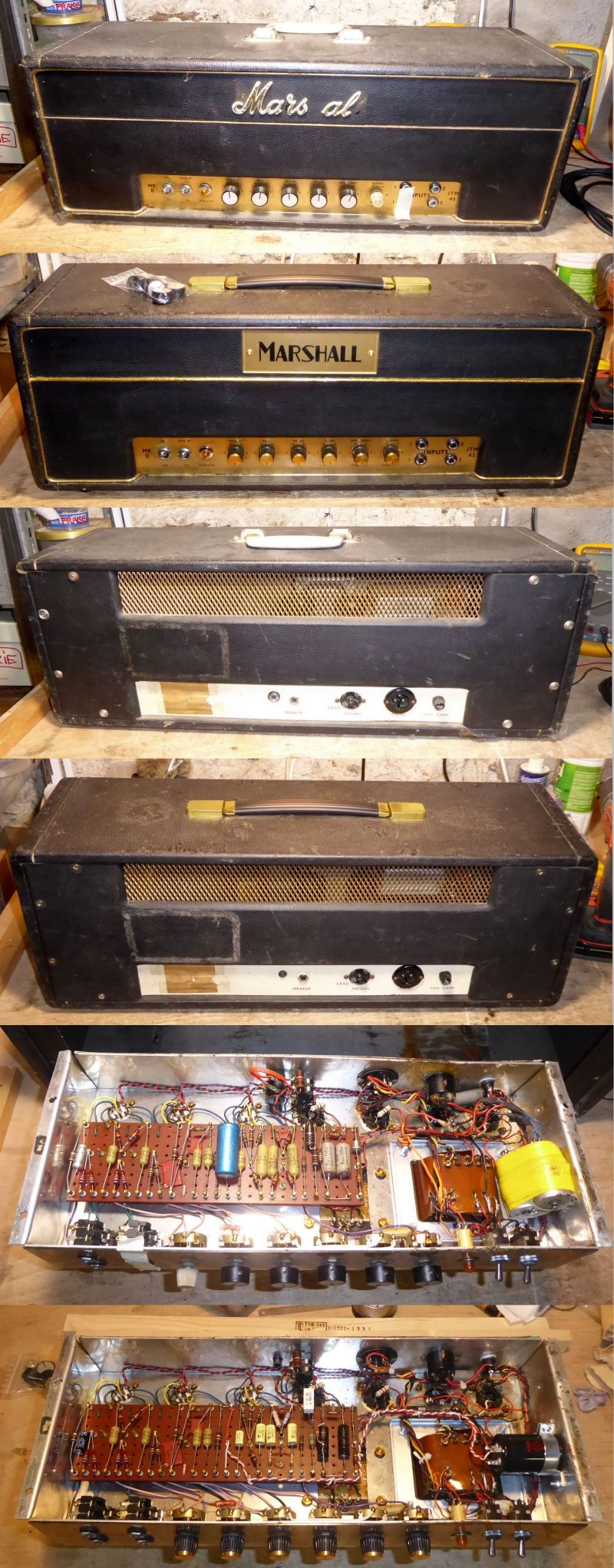
Below, a 1964 Marshall JTM45 that I had on my bench for repair / restoration this summer. Alterned Before/After pictures :
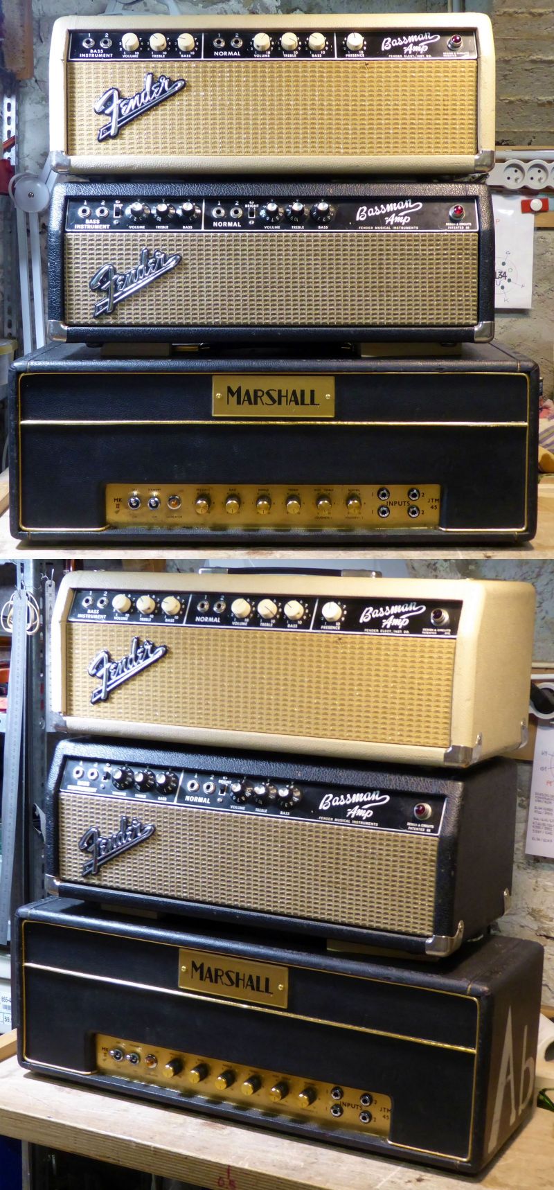
The JTM45 with some Friends of the same era :
T
Last edited:
Other than in a follower configuration they just take off at some frequency between DC and about 40 MHz.
Why don't they oscillate when used as cathode followers? With a bit of load capacitance and some inductance in the grid/gate/base lead, a cathode/source/emitter follower becomes a Colpitt oscillator.
That reminds me what happened when I tried to triode connect a PL500 which seemed to defy ohm's law. Anode current and voltage across the cathode resistor just did not go together. Until I finally noticed that a DMM more than a meter away, not connected to anything at all, went into OL overload each time the tube was on. Some 15cm of cable between top cap and socket has just the perfect combination of L and C to turn a Hot into a VHF jammer. Lesson learnt: Screen stoppers required when triode connecting a top capoed HOT.
They often DO oscilate as cathode followers. It's just that sometimes they can be made not to oscillate. Almost everything I did in a conventional grid driven circuit had serious stability problems as soon as I got the current up to where there was some real Gm. On anything below 600 volts the grid must be positive to get 50 mA or so of current to flow.Why don't they oscillate when used as cathode followers? With a bit of load capacitance and some inductance in the grid/gate/base lead, a cathode/source/emitter follower becomes a Colpitt oscillator.
I have not tried these tubes in an UNSET circuit yet, but it's on my list of things to do.
Yes cathode followers can oscillate in Colpitts mode, and also if the Real part of the grid impedance becomes negative (due to phase shifts in the load on the cathode).Why don't they oscillate when used as cathode followers? With a bit of load capacitance and some inductance in the grid/gate/base lead, a cathode/source/emitter follower becomes a Colpitt oscillator.
Small values of grid stopper will suppress these modes
Ys, I think it's an RC noise filter too. The grid circuit has a somewhat hi-Z and labyrinthine connexion back to groundThat reminds me of the Brook 10C circuit but, curiously, it does use grid stoppers in front of the cathode followers. Maybe it's for filtering out high frequency with the two .001uf caps.
Whether a k-follower is sensitive to oscillation or not really depends on what you have in the tail. When the cathode load is capacitive, the grid side real part becomes negative. Resistance in either place (grid or cathode) damps the circuit and can prevent oscillation. With the usual values of tail resistor used in audio work, the circuit is well enough damped not to oscillate even without a stopper. But if your tail resistor becomes highly inductive it may not be enough of a “resistor” at the frequencies in question, and at HF all the stray capacitances dominate. If a CCS tail is used (to improve performance) it’s impedance at audio is high and most certainly goes pure capacitive at VHF/UHF/uW. Guaranteed oscillator with no grid stopper.
Last edited:
I built a cathode follower from one of the other (not 6HV5A) similar beam regulator triodes and tested it with a HP204C audio oscillator and a 600 ohm OPT being used only as a choke in the cathode. I got all sorts of squirrelyness and weird sounds when I connected it to a speaker which was wired directly across the OPT primary. I replaced the audio oscillator with the headphone output of a Sony Discman and got quietness. Cranking the Discman to full output brought sound, clean undistorted sound with loose flabby bass. Power output was probably in the milliwatts and the tube needed a lot of B+. I don't remember how much, but likely way over 500 volts. I had 1 KV and a 2 KV power supplies back then. Attempting to use the OPT in the plate circuit in "normal" OPT configuration created a full on TV and radio jammer, probably due to the point to point construction with flying leads. No clip leads though, and very few parts just a grid resistor and blocking cap at the input. A 3K ohm Transcendar OPT did the same.
This is one group of tubes that I have yet to tame. Nobody has bought any of them in 10 years of taking them to hamfests and I have a good size box full, collected one at a time over maybe 40 years.
This is one group of tubes that I have yet to tame. Nobody has bought any of them in 10 years of taking them to hamfests and I have a good size box full, collected one at a time over maybe 40 years.
As long as beam triodes take 2KV to make any real use of people are going to continue to stay away from them. Self included. If I ever start doing anything with that kind of B+ it will be transmitter triodes. At least you can make some real power with those, and might be worth spending $1000 apiece on appropriate output iron. And having to work with one hand tied behind my back. Maybe less chance of getting 2 kV across your heart, but far more chance of dropping a tool in the middle of your work and vaporizing it (in your face).
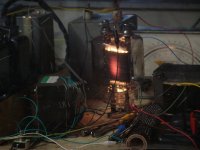
I even shrugged off transmitter tubes a few years ago. I sold the remains of the 845 / 211 amp that I built almost 20 years ago at the last hamfest along with most of the tubes that would fit in it. The reality of my degrading hearing has led me to realize that I can't hear the difference between a 300B and a triode wired 6L6GC any longer, so a lot of the big voltage stuff has been sold. I still have a few 833As in a box somewhere along with a custom Transcendar output transformer for them and a power transformer out of a Harris transmitter to really wake up an 833A. In reality, they are still here because nobody seems to want them cheap and that 200 watt SE triode guitar amp is way too far down the unfinished projects list. The "200 watt SE OPT" is just to the right of the glowing tube. Glow at that level is normal for these tubes, but forced air cooling is recommended for the terminals. A custom Vice Grip tube socket is not recommended. Neither are the clip leads. There is 1500 volts in that yellow one! These pictures are about 20 years old, and I haven't built it yet.........
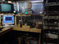
Note the 1/4 inch Lexan "blast shield" between me and the electricity when in use (except for a few carefully taken pictures).
Note the 1/4 inch Lexan "blast shield" between me and the electricity when in use (except for a few carefully taken pictures).
Attachments
I used to hide behind a blast shield when testing TRANSISTOR amps before I discovered the light bulb limiter, in 1979. Pieces of rectifier in my face when Ge transistors went into second breakdown was when that started. Oscillating amplifiers had similar mishaps. I think your 6LR8 furball should have been behind a blast sheild too - if for no other reason than to keep the dog/cat out of it.
The rack mounted thing with the 50 pound transformer on it was a power supply from an old Motorola tube type VHF transmitter. It was RATED at 1500 volts at 500 mA. It contained a good bit of stored energy on top of that, and thanks to that high quality yellow clip lead there was the storage capacitor from a cardiac defibrillator connected across its output. There were several possible scenarios where something could go into a "spontaneous unscheduled rapid decomposition", but the real reason was to keep the head of the guitar from contacting any of the exposed high voltage. The cheapie guitar cable would likely be the "fuse" in that kind of a short, and I would be left holding the electricity. A guitar player's left hand assumes a "death grip" on the neck and it is often impossible to let go of a guitar in an electrocution scenario. Players have been killed by hot chassis guitar amps from the 1950's in this manner.
I have had two vacuum tubes explode due to stupid arithmetic. Both were 6HJ5's subjected to several hundred watts of dissipation leading to a tube arc that vaporized the plate pin where it passed through the glass.
Many years ago, I got a box full of early vintage Chinese made KT88's, cheap. Most of them were very poorly made and about 5 out of nearly 100 would live at 100 watts per pair output power. I used them in small amps that ran at 30 to 35 WPC and even at that level "stuff" happened. I popped a shiny new one into a working amp only to see a nice Chinese Fireworks display going on inside which eventually led to the glass shattering.
As you stated semiconductors often explode or turn into carbonized plastic fireballs far better than vacuum tubes. Most of my off line experiments were first powered up with an inverted coffee mug over the semis. Ever managed to spit molten metal through the lid of a metal cased TO-3?
The 6LR8 furball was first tested on my Fluke 407D power supply. It uses 3 X 807s for the pass tubes and they are the 1960's originals, so the Fluke is generally incapable of real electrical mayhem as if the old Knight Kit KG-664 which has all new caps and 4 X 6L6GC pass tubes.
Both house cats in Florida were trained to stay out of that room, as was my daughter and her friends, though different means were used. Cats are typically smart enough to remember something they didn't like if subjected to it long enough. It took about a year to drain the dumb one that he would receive a water blast from a squirt gun if he tried to sneak into the room. That and my poor guitar playing kept the cats out. The only cat here lives outside. She has never tried to come inside, but she will whine outside the back door for some attention sometimes.
Solid state amps have a tendency to throw molten pieces when they oscillate because of the high common conduction current that results from running power transistor emitter followers above their frequency capability. Turn off times are too slow, so the NPN and PNP halves are on (hard) at the same time. Fortunately, that particular failure mode doesn’t happen in a push pull tube amp. When they self- oscillate the plate circuit impedance goes high, which might melt a screen due to insufficient plate current at clipping or run the transformer voltage too high. Either could be destructive without protections but those can be implemented. More often it’s a basic feedback nyquist issue and the resulting frequency wont blow anything up. Plenty of other reasons for things to go south, especially when the last term of 0.5*CV^2 dominates how much energy is involved.
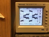
I’ve run into more than my share of local oscillations in cathode coupled circuits. Nothing destructive, but often initial symptoms defy explanation. Here’s a pic of a pair of complementary k-followers breaking in and out of oscillation at a 60 Hz rate. Driven by the instantaneous h-k voltage. Yes, it as elevated to the -68V bias. But the audio signal was large, and when it got large enough the oscillation started. That shifted the bias dramatically, and shifts back when the oscillation cuts out. There is hysteresis. But the oscillation frequency was so far above my scope’s capability you can’t see it. Just the audio riding on it. Solution was to move the bias PCB with the pots right between the two tube sockets and use the resistor leads to connect the board to the socket. Instant grid stopper.
When I saw something similar happening on an LTP using a silicon current source I instantly thought sh*+, it’s oscillating - and no way to add a grid stop because the feedback resistors are already using the available terminals. I put a 1k resistor in the tail , which would be unnecessary for the audio since the 2SC3902’s Zout is already high. But it got rid of the RF troubles.
Attachments
okPlease.
I'll work on an example. for you, but:
Rs = ( Ebb - Ec2 ) / Ip Xc2
where
Ebb is B+ applied to the plate resistor.
Ec2 is voltage of screen grid (if triode add bias voltage at idle of grid)
Xc2 is grid element correction factor ( Xc2 ~ ic2/Ip ~ gm1/Gm1 )
Ip is plate current
Ic2 is total instantaneous screen grid current
gm1 is transconductance at operating voltage
Gm1 is average transconductance in operation
even though its easier to just use a 1M potentiometer temporarily as the grid stop and adjust till you find the resistance with the lowest noise floor especially when used and nos tubes are used
Last edited:
Those were from class notes eons ago. The book we used in class is called "Conductive Curve Design Manual". As it was one of those books the school program used, but I couldn't buy at the book store back then. So decided to write down its tittle in case I would want it in the future, but I never got it.
Show me how to make one of those beam triode regulator tubes like the 6HV5A unconditionally stable without resistors, chokes and RF bypass caps with near zero lead length on nearly every pin.
Applying a horizontal output tube sometimes is harder than most would think.
https://www.worldradiohistory.com/B...nce-Curve-Design-Manual-Pullen-1958-Adobe.pdf
This is a calculation of the screen resistor.
Minimum noise will be with 0R grid resistor, however this can result in VHF oscillation and/or rectification of radio stations. The equivalent grid noise resistance for a triode is approximately 2.5/gm so using a grid resistor of somewhat less than this will be the thing to do. There's also plate noise too to consider. 1meg is noisy as that's what guitar inputs use before you plug the pickup in.
Show me how to make one of those beam triode regulator tubes like the 6HV5A unconditionally stable without resistors, chokes and RF bypass caps with near zero lead length on nearly every pin - Easy don't apply any heater voltage and keep it in its box.
Last edited:
Show me how to make one of those beam triode regulator tubes like the 6HV5A unconditionally stable without resistors, chokes and RF bypass caps with near zero lead length on nearly every pin. With a Gm of 65000 and a Mu of 300 those things are secretly oscillating while sleeping in their cardboard boxes. Just pop one of them into your favorite circuit, and SURPRISE! After spending a lot of time with those things, I gave up, twice. Other than in a follower configuration they just take off at some frequency between DC and about 40 MHz. Even if it's undetectable with test equipment, if the quiescent current in a circuit changes as you move your hands or a piece of metal over the design, without touching it, the design is oscillating. Sometimes the oscillation will stop when a scope probe touches the circuit. Often connecting resistors, caps or a bent coat hanger into that circuit at that point will NOT stop the oscillation. It's secretly laughing at you!
The plate voltage area I just don't like to mess with often(900v B+), but yes, I made one as an audio pre-driver before to drive a transmitting tube (845).
- Home
- Amplifiers
- Tubes / Valves
- Does audiophile tube builders know what a grid stop is for?